
Executive Summary
A practical guide to surgical light installation requirements: ceiling load and moment, clear height, arm clearance, electrical supply, trade coordination, and an acceptance checklist.
Most operating-room lighting failures I get called to inspect were never caused by the light itself. The LED engine, optics, and control board were fine. The problem was above the ceiling: an undersized support, a mounting plate that was never leveled, a junction box in the wrong place, or a structural deck that deflected every time the arm swung. Surgical light installation requirements are decided long before the fixture arrives on site — usually by people who never read the luminaire’s pre-installation manual: the structural engineer, the mechanical contractor, the electrician, and the HVAC designer. When those trades guess instead of coordinate, you get arm drift, a lighthead that will not hold position, cracked ceiling panels, and a sign-off that stalls for weeks.
When the ceiling interface is the constraint, the retrofit vs replace decision changes: see our surgical light upgrade guide.
For teams working through the same decision, see our what to specify for light accessories.
This guide is written from the installer’s and project engineer’s point of view. It walks through the ceiling and structural conditions a ceiling-mounted surgical luminaire actually needs, the installation sequence, the way the light trade coordinates with civil structure and HVAC, and a practical acceptance checklist you can take into the room. I reference the governing standard — IEC 60601-2-41 for surgical luminaires — and the real load, electrical, and clearance figures from manufacturer pre-installation documents, so you can sanity-check your own drawings. If you are still selecting the fixture, start with our LED surgical light range, because the mounting load, arm reach, and electrical data all flow from the specific model you specify.
One point up front: the owner’s contractor carries final responsibility for the strength and rigidity of the ceiling structure. The manufacturer publishes the loads and mounting geometry; the building team delivers a support that meets them and complies with local code.
Why Surgical Light Installation Requirements Are a Structural Problem First
A ceiling-mounted surgical light is not a downlight. It is an articulated mechanism hanging from a single point, carrying one, two, or three lightheads on a multi-joint arm, repositioned dozens of times a day by surgeons who are not thinking about the ceiling. The support sees three forces at once: a steady vertical dead load from the suspension and heads, a dynamic off-center moment as the arm swings the head away from the mounting axis, and small repeated loads each time someone grabs a handle. The off-center moment is the one most people underestimate, because it grows with arm reach — the further the head travels from the column, the larger the overturning force at the mounting plate.
This is why manufacturer pre-installation manuals state the structural requirement in two numbers, not one. A representative ceiling-mounted LED surgical lighting system documents a structural mount designed for a vertical load of around 300 lbs (roughly 136 kg) for a triple-head configuration — a single head being significantly less — together with an off-center moment on the order of 960 ft-lbs. Those are not the fixture’s weight; they are the design envelope the support must resist without deflecting. If the structure flexes, the symptom appears at the lighthead: the arm drifts, the head sags, and the surgeon keeps readjusting. The 2021 edition of IEC 60601-2-41 added an explicit requirement for acceptable lighthead drift when attached to the suspension system, so drift is no longer just an annoyance — it is a conformance issue the support structure can cause even when the light’s own brakes are perfect.
If a brand-new surgical light “won’t hold position,” do not assume the arm brakes are faulty. More often the root cause is a mounting plate installed out of level or a support that deflects under the off-center moment. Level the casting and stiffen the support first; only then touch the friction adjustments.
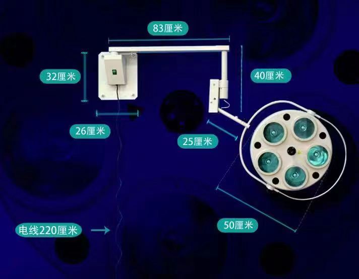
Ceiling Load Calculation: What the Support Really Has to Carry
Load calculation starts with the luminaire data sheet and ends with a signed structural note. You need four inputs: the dead weight of the full suspension assembly (casting, drop tube, arm segments, and heads), the maximum off-center moment the manufacturer specifies, a dynamic factor for daily repositioning, and any local seismic or code multiplier. The manufacturer supplies the first two; the structural engineer applies the rest and then proves the deck, beam, or slab at the mounting point can deliver the capacity within an acceptable deflection limit.
Two points get missed constantly. First, the load is eccentric, not centered on the bolt group, because the arm reaches out — a support that is fine in pure compression can still deflect under the overturning moment, so the check must be a moment check, not just a weight check. Second, the number of heads changes the envelope dramatically: a single-head solo mount is “significantly less” than a triple-head mount in both load and moment, so calculate against the exact configuration you are buying. The table below summarizes typical planning figures and where each comes from.
| Installation Parameter | Typical Planning Figure | Source / Who Confirms |
|---|---|---|
| Vertical design load (triple-head) | ~300 lbs / ~136 kg (single head significantly less) | Manufacturer pre-installation manual |
| Off-center (overturning) moment | ~960 ft-lbs for a representative triple system | Manufacturer manual; verified by structural engineer |
| Mounting plate levelness | Level within tolerance; shim if ceiling surface is not level | Installer, to prevent arm drift |
| Supply circuit (120 VAC class) | 110–120 VAC, 50/60 Hz, single phase, 3-wire, ~700 W @ ~6.4 A | Manufacturer electrical spec |
| Supply circuit (230 VAC class) | 220–240 VAC, 50/60 Hz, single phase, 3-wire, ~700 W @ ~3.2 A | Manufacturer electrical spec |
| Lighthead positioning envelope | ~360° horizontal; vertical roughly +15° to −65°; head rotation ~330° | Manufacturer mechanical spec |
Treat these figures as a planning benchmark, not a substitute for your model’s data sheet — different suspensions, drop lengths, and head counts move every number. What matters is that the structural note on the drawings references the actual luminaire manual and the governing code, so the inspector can trace the calculation.
Embedded Parts, Interface Plates, and the Conversion Layer
Between the raw building structure and the luminaire’s ceiling casting there is almost always a conversion layer — embedded parts cast into concrete, a steel interface (mounting) plate, threaded rods, or a fabricated adapter bridging the beam to the fixture’s bolt pattern. This is where civil/structural work and the medical-equipment trade must agree on dimensions before concrete is poured or steel ordered, because retrofits are expensive and sometimes impossible without opening the ceiling.
Manuals are specific about this hardware. Where an interface plate is used, a typical instruction is to use high-strength threaded rods (for example 5/8-11 A325 rod) with matching hex nuts and washers, and to follow the published mounting dimensions for the casting exactly. The hardware grade matters because ordinary fasteners can loosen under the repeated dynamic moment of normal use — precisely the failure mode that produces an unstable arm/head assembly. Three rules keep this stage clean:
- Confirm the bolt pattern and embed depth before the structure is closed up. The luminaire’s ceiling casting has fixed mounting dimensions; the embedded anchors or interface plate must land exactly there. A few millimeters of error becomes a field-drilled compromise that weakens the connection.
- Specify the fastener grade the manual calls for. High-strength rods and proper washers are not optional — they resist the cyclic off-center load. Substituting generic hardware is a common, avoidable cause of loosening and drift.
- Plan the leveling shim allowance. If the structural mounting surface is not level, the casting must be shimmed to level. Skipping this is one of the most frequent causes of unwanted arm drifting during use.
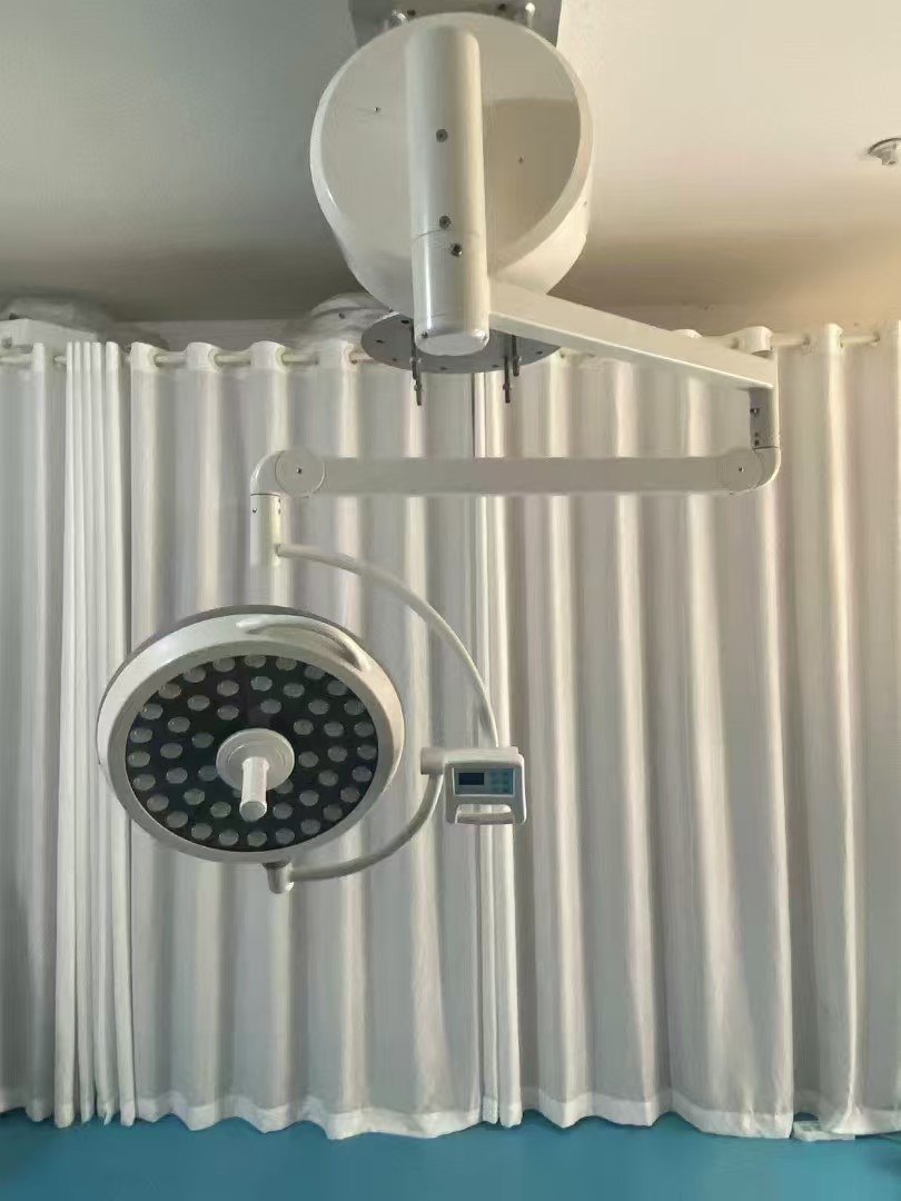
Ceiling Height, Clear Height, and Arm Movement Space
Clear height is the second most common installation mistake after structural under-sizing. “What ceiling height is needed for surgical lights?” has no single universal answer, because it depends on the suspension drop length, the arm geometry, and the required working position of the head over the table — but it is governed by code and ergonomics and must be checked on the drawings. Hospital design guidance such as the FGI Guidelines and the minimum-height-with-fixed-ceiling-equipment clause in model building codes set the operating-room baseline, and the luminaire’s suspension has to fit within that envelope while still placing the lighthead at a usable distance above the surgical field.
The practical calculation is the ceiling rod (drop tube) length. Manuals include a dedicated ceiling-rod calculation for solo, duo, and trio mounts for exactly this reason: the rod must be long enough to bring the head into its working range over the table, but not so long that it over-reaches, clips the laminar-airflow canopy, or forces the arm past its mechanical limits. Check the supplied rod length against the finished ceiling height and table position before installation, not after.
Arm movement space is the related, often-overlooked half of the problem. A typical ceiling-mounted head offers roughly 360° of horizontal positioning, a vertical tilt around +15° to −65°, and about 330° of head rotation. The room has to provide clearance for that full envelope: no clash with the laminar-flow diffuser, the secondary light, the display arms, the anesthesia pendant, or the door swing.
Coordinate the light’s arm sweep against the laminar-airflow canopy and the pendant arms before the ceiling is closed. A head that clips the diffuser frame or a monitor arm is a coordination failure, not a product defect — far cheaper to move a hanger on paper than to re-route a duct later.
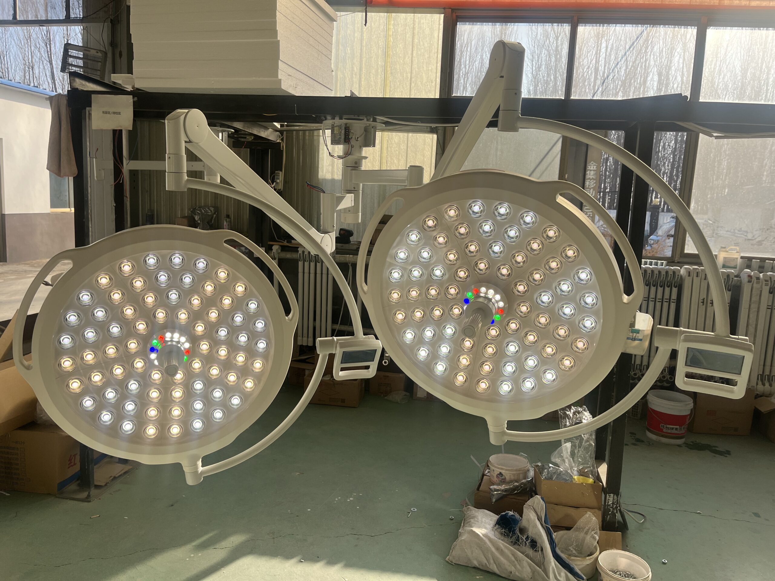
Electrical Supply, Wiring, and Junction Box Placement
The electrical side of surgical light installation requirements is modest in amperage but unforgiving in detail. A representative LED surgical lighting system draws on the order of 700 watts: at 120 VAC roughly 110–120 V, 50/60 Hz, single phase, three wire, about 6.4 amperes; at 230 VAC about 220–240 V, 50/60 Hz, single phase, three wire, about 3.2 amperes. The current is small, but three things still have to be right: a dedicated circuit, a correct protective earth, and a junction box that lands where the luminaire’s power box expects it.
Manufacturer guidance is to mount the power box directly over a standard junction box where possible, and otherwise to run the supply lines per applicable codes. The lighting system should sit on its own circuit with an integral breaker that acts as the local disconnect. The protective earth matters for safety: the mains ground conductor (typically the green wire with a ring terminal) must be fastened securely to the mounting plate with a screw and lock washer — a missing or loose earth is a shock hazard and an instant commissioning failure. The checklist that keeps the electrical trade aligned:
- Dedicated circuit with integral breaker sized to the luminaire’s nameplate, acting as the local main disconnect.
- Correct voltage class confirmed before energizing — 120 VAC and 230 VAC versions have different current ratings and must match the site supply.
- Reliable protective earth bonded to the mounting plate with the ring terminal, screw, and lock washer.
- Junction box positioned to align with the power box, so conductors are not stretched, pinched, or left dangling inside the suspension.
- Control and accessory wiring routed cleanly through the arm and ceiling casting per the manual’s cable-termination steps, with strain relief.
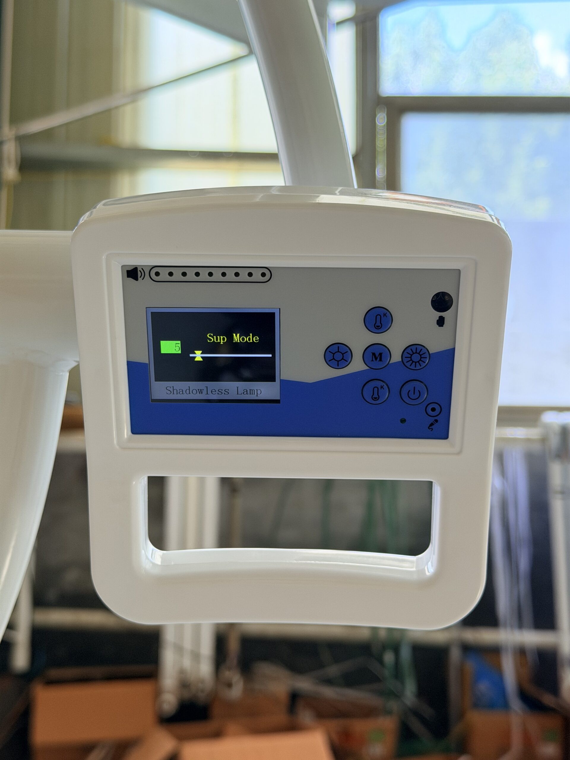
Step-by-Step Installation Sequence
The installation follows a fixed order, and skipping steps is what produces the call-backs. Installation and repair should be performed by a qualified mechanical contractor, and the full pre-installation manual reviewed before anyone starts. The sequence below is the field order I use, aligned with the way manufacturer manuals organize ceiling-mount installation.
Step 1 — Verify the site before unpacking
Confirm the structural mount meets the published vertical load and off-center moment, that the surface is level (or shims are on hand), that the junction box is correctly placed, and that the dedicated circuit is present and de-energized. Check the supplied ceiling-rod length against the finished ceiling height and table position. A mismatch caught here costs minutes; caught after assembly, it costs days.
Step 2 — Install and level the ceiling casting / interface plate
Fix the casting or interface plate to the verified support using the specified high-strength hardware and published mounting dimensions, then shim to level if the structure is not level. This is the single most important step for preventing later arm drift, so confirm level before proceeding.
Step 3 — Assemble the suspension and arm
Install the drop tube or extension, then the arm segments, inserting and locking the dowel pins per the manual. Route and terminate the arm cables with strain relief before the head goes on, so conductors are not trapped or stretched through the full range of motion.
Step 4 — Make the electrical connection
Land the supply conductors on the power box, bond the protective earth to the mounting plate with the ring terminal and lock washer, and verify the dedicated breaker acts as the local disconnect. Keep the circuit de-energized until the mechanical assembly is complete and inspected.
Step 5 — Mount the lighthead and remove shipping locks
Attach the lighthead to the arm and remove the locking pins and shipping restraints. Manually walk the head through its full horizontal, vertical, and rotation envelope to confirm there is no clash with the diffuser, second light, displays, or pendants.
Step 6 — Adjust, energize, and function-test
Set arm and head friction so the head holds position anywhere in its travel without drifting, then energize and test on/off, dimming levels, and any endo or shadow-control modes. Re-check level and drift after the first few repositioning cycles.
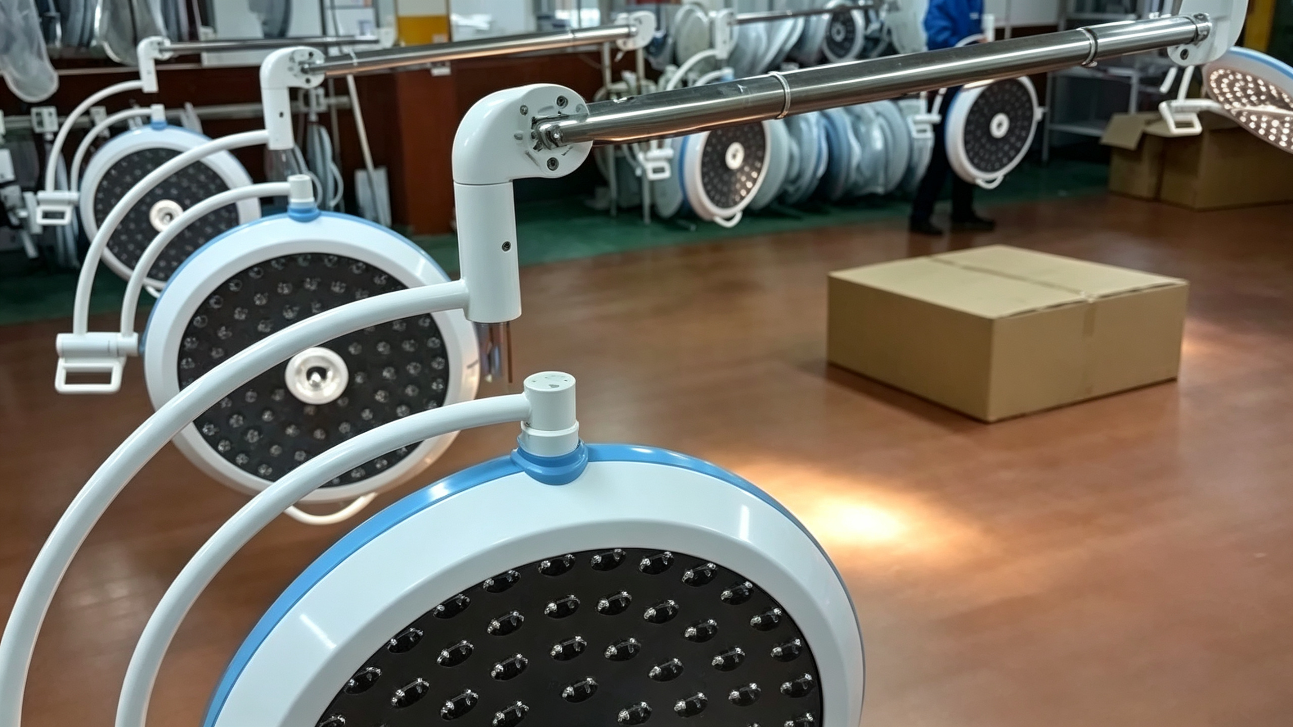
Coordinating With Civil Structure and HVAC
A surgical light never installs into an empty ceiling. It shares the space with the structural deck, the laminar-airflow canopy and diffusers, the return-air path, medical-gas and anesthesia pendants, surgical displays, sprinklers, and general lighting. The light trade has to coordinate with civil/structural and HVAC early, because fixes are cheap on paper and brutal after the ceiling is closed.
With the structural/civil team, the items are support capacity and embed geometry: confirm the beam or slab at the mounting point can take the vertical load plus off-center moment, agree the embedded-anchor or interface-plate locations and depths before pour, and confirm who signs the structural note. With HVAC, the dominant conflict is the laminar-airflow canopy: the head must reach the surgical field without clipping the diffuser frame, and the suspension and arm must not block supply airflow or create a dead zone over the sterile field. The practical coordination list:
- Overlay the light’s arm-sweep envelope on the reflected ceiling plan and check it against the laminar canopy, return grilles, pendants, and display arms.
- Lock the mounting point relative to the table and the canopy centerline, so the head reaches the field within its drop-length range.
- Confirm structural embeds before concrete or deck closure, and keep the signed load calculation on file for inspection.
- Sequence the trades: structure and embeds first, HVAC rough-in coordinated around the suspension, then the light installation, then ceiling closure.
- Protect the sterile airflow: verify the suspension does not obstruct the diffuser or create turbulence over the wound zone.
For how the light fits into the whole room — clearances, zoning, and airflow — our guides on operating-room layout and dimensions and laminar-airflow operating-room design cover the surrounding geometry in detail.
Commissioning and Acceptance Checklist
Acceptance is where surgical light installation requirements get proven rather than assumed. Walk the room against a written list and sign nothing until each item passes. The checklist below combines the structural, mechanical, electrical, and functional checks into one sign-off sheet.
- Structural: mounting plate level and secure; specified high-strength hardware installed; signed load calculation (vertical load + off-center moment) on file and traceable to the luminaire manual and local code.
- Mechanical: correct ceiling-rod length for the room height; arm and head move through the full published envelope with no clash against diffuser, second light, displays, or pendants.
- Drift: lighthead holds position anywhere in its travel and does not sag or creep after repeated repositioning (per the IEC 60601-2-41 drift expectation).
- Electrical: dedicated circuit with integral breaker acting as local disconnect; correct voltage class; protective earth bonded to the mounting plate; junction box aligned with the power box.
- Functional: on/off, dimming steps, and any endo/shadow modes operate correctly; controls respond as specified.
- Documentation: as-built mounting drawing, load note, circuit identification, and the manufacturer’s commissioning record handed over to facilities.
If you are running a full room build rather than a single-light retrofit, the same discipline scales up: our walkthrough of operating-room equipment installation and commissioning covers how lights, tables, and pendants sign off together, and our turnkey operating-room solution bundles the coordination so one team owns the whole envelope from structural interface to final acceptance.
Conclusion
Surgical light installation requirements are mostly decided before the fixture arrives: the ceiling must carry the vertical load and the off-center moment without deflecting, the casting must be leveled, the drop length must match the room height, the arm must clear the laminar canopy and surrounding equipment, and the electrical rough-in must deliver a dedicated, correctly earthed circuit at the right voltage. Get the structure and coordination right and the light performs the way its data sheet promises; get them wrong and no amount of arm adjustment will fix a drifting head. The standard that ties it together is IEC 60601-2-41, and the discipline that makes it work on site is a written load calculation, a coordinated reflected-ceiling plan, and an acceptance checklist signed only when every item passes. If you want a manufacturer that supplies the luminaire together with the mounting loads, the pre-installation geometry, and the coordination support, talk to our project team before your next ceiling is closed up.
Frequently Asked Questions
What are surgical light installation requirements?
They are the structural, dimensional, and electrical conditions the ceiling and room must meet before a ceiling-mounted surgical luminaire is fitted: a support sized for the luminaire’s vertical load and off-center moment, a leveled mounting plate or interface plate with the correct high-strength hardware, a ceiling height and drop-tube length that place the lighthead in its working range, clear arm-sweep space around the laminar canopy and other equipment, and a dedicated, correctly earthed supply circuit. The governing product standard is IEC 60601-2-41, and the building side must comply with local code.
How much ceiling load does a surgical light need?
It depends on the configuration, but a representative triple-head ceiling system documents a structural mount designed for roughly 300 lbs (about 136 kg) of vertical load plus an off-center moment on the order of 960 ft-lbs, with a single head being significantly less. The decisive number is the overturning moment, which grows with arm reach, so the support must be checked for moment and deflection — not just weight — by a structural engineer against the specific model’s data sheet.
What ceiling height is needed for surgical lights?
There is no single universal figure: the required clear height is set by hospital design guidance such as the FGI Guidelines and the minimum-height-with-fixed-ceiling-equipment clauses in model building codes, combined with the luminaire’s suspension drop length and arm geometry. The practical task is to choose a ceiling-rod length that places the lighthead at a usable distance over the table within the room’s finished ceiling height, while leaving clearance for the arm’s full horizontal and vertical sweep and the laminar-airflow canopy.
How is a surgical light mounted to the ceiling?
A ceiling casting or interface plate is fixed to a verified structural support using the manufacturer’s published mounting dimensions and specified high-strength threaded rods, nuts, and washers, then shimmed level. The drop tube or extension and the articulated arm are assembled and pinned, the arm cables are routed and terminated, the lighthead is attached and its shipping locks removed, and the friction is adjusted so the head holds position. Installation should be performed by a qualified mechanical contractor following the pre-installation manual.
What electrical supply do surgical lights need?
A typical LED surgical lighting system draws around 700 watts: about 110–120 VAC, 50/60 Hz, single phase, three wire at roughly 6.4 A for a 120 VAC unit, or about 220–240 VAC at roughly 3.2 A for a 230 VAC unit. It should be served by a dedicated circuit with an integral breaker acting as the local disconnect, with the protective earth securely bonded to the mounting plate, and the junction box positioned to align with the luminaire’s power box.
You May Also Like...

After-Hours Maintenance Strategy: Minimizing OR Downtime
Operating room downtime is expensive because an idle OR still burns staff, overhead and scheduled...

Operating Table Battery Replacement: Procedure and Intervals
Operating table battery replacement is the routine swap of the integrated backup battery that keeps...

Trolley Lock Cylinder Maintenance: Keyed and Push-Lock Types
Medical trolleys fail at the lock. Not the frame, not the casters, not the drawers...