
Executive Summary
A practical guide to medical gas pipeline design for operating rooms: outlet schedules, zoning and valve boxes, pipe sizing per ISO 7396-1 / HTM 02-01 / NFPA 99, pendant integration, and commissioning.
Ask a hospital project team what keeps them up at night during an operating room build, and they rarely mention the surgical lights or the table. They mention the medical gas pipeline. It is the one system that is almost entirely hidden behind the wall by the time the room is handed over — and the one system where a design mistake discovered after commissioning means opening finished walls, re-validating the whole network, and delaying the first surgery by weeks. I have watched a 12-OR project lose two months because the vacuum riser was sized for the original room count, not the two endoscopy rooms added during design development. Nobody caught it until pressure testing.
The frustrating part is that medical gas pipeline design for operating rooms is not mysterious. The rules are well documented in ISO 7396-1, NFPA 99 (Health Care Facilities Code), and the UK’s HTM 02-01. What goes wrong is coordination: the pipeline designer, the pendant supplier, the OR planner, and the contractor each hold one piece of the puzzle, and the gaps between them become change orders. When we deliver ceiling-mounted medical pendants as part of an OR package, the gas outlet schedule on the pendant is often the first place where design intent and clinical reality collide.
This guide walks through the design process the way we run it on turnkey projects: standards first, then outlet counts and zoning, pipe sizing, valve and alarm placement, pendant integration, and finally testing and verification. Whether you are a hospital engineer, a consultant, or a distributor scoping a project, this is the sequence that prevents the expensive surprises.
1. Know the Standards Before You Draw a Single Line
Every medical gas pipeline system (MGPS) design decision traces back to a standard. The three you will encounter most:
- ISO 7396-1:2016 — the international standard for pipeline systems for compressed medical gases and vacuum. It governs source equipment, distribution, monitoring, and terminal units. Most national standards are harmonized with it or reference it directly.
- NFPA 99 (Health Care Facilities Code) — the dominant framework in North America and many Middle East projects. It defines risk-based system categories (Category 1 for spaces where failure could cause major injury or death — which includes every operating room) and prescribes zone valves, alarms, and testing.
- HTM 02-01 (UK) — arguably the most operationally detailed guidance anywhere. Part A covers design, installation, validation, and verification; its pressure-loss tables and diversity-factor method are used as a de facto reference even on projects outside the UK.
Beyond the MGPS-specific codes, remember the edges of the system: EN ISO 9170 for terminal units, ISO 5359 for low-pressure hose assemblies, and the medical electrical safety context of IEC 60601-1 for any powered pendant or alarm panel mounted in the room. If the project ships to Europe, the overall installation also sits under the MDR 2017/745 umbrella for the devices that connect to the pipeline.
Experience note: decide at kickoff which standard governs the project and write it into the specification. Mixed-standard projects — an NFPA-style zone valve philosophy with HTM-style diversity factors — produce drawings that pass no one’s review.
2. Step 1 — Build the Outlet Schedule From the Clinical Workflow
The single most important document in OR medical gas design is not the piping drawing. It is the schedule of provision — a room-by-room table of which gases, how many outlets, and where. Get this signed off by the clinical users before pipe sizing starts, because every later calculation depends on it.
For a modern general operating room, a typical provision includes:
- Oxygen (O₂): 2–4 outlets — anesthesia machine, plus spare points for ventilators and emergency use.
- Medical air (MA-4 / 4 bar): 1–2 outlets for anesthesia and ventilation.
- Surgical/instrument air (SA-7 / 7 bar): 1 outlet where pneumatic tools (drills, saws) are used — orthopedic and neuro rooms only; do not blanket-specify it everywhere.
- Nitrous oxide (N₂O): 1 outlet where the anesthesia technique requires it; many new builds are dropping N₂O entirely in favor of AGSS-only strategies.
- Medical vacuum: 2–4 inlets — anesthesia suction, surgical field suction, and a spare. Vacuum is the service most often under-provided.
- AGSS (anesthetic gas scavenging): 1 dedicated disposal terminal per anesthesia position — mandatory wherever inhalational agents are used.
Split outlets between at least two physical locations: the anesthesia pendant or boom on one side, and a wall panel or surgical pendant on the other. If every oxygen outlet in the room hangs off one pendant, a single pendant fault or a blocked booms rotation takes the whole gas supply with it. Redundancy of location is as important as redundancy of count.
3. Step 2 — Zone the System and Place the Valves
Zoning is the safety architecture of the pipeline. The principle is simple: you must be able to isolate any one operating room (or a small group of rooms) for maintenance or emergency without interrupting gas to adjacent critical areas. In practice this means:
- Area/zone valve service units (AVSUs): a lockable, glass-fronted valve box per zone, located in a corridor or staffed area immediately outside the rooms it serves — never inside the OR itself, never behind a locked plant room door. Under NFPA 99, zone valves sit downstream of the riser valve and serve each anesthetizing location group; HTM 02-01 follows the same corridor-access philosophy.
- Logical zone boundaries: group by clinical dependency, not by drawing convenience. An OR plus its dedicated anesthesia prep room is a sensible zone; an OR plus the ward across the corridor is not.
- Labeling: every valve box labeled with the gas, the area served, and the rooms affected. During an emergency shutdown at 2 a.m., nobody reads a drawing — they read the box.
Alarm design follows the same zone logic. Area alarms (local alarm panels) cover each zone’s pressure switches; master alarms at a continuously staffed point (typically the engineer’s office and telephone exchange) cover source plant status and main line pressure. The area alarm panel for an OR suite belongs in the corridor or control desk where circulating staff actually stand — an alarm annunciating in an empty equipment room is a decoration, not a safety device.
4. Step 3 — Size the Pipework: Flow Rates and Pressure Drop
Pipe sizing is where the schedule of provision becomes engineering. The method, common to HTM 02-01 and consistent with NFPA 99 practice, is:
1. Assign a design flow to every terminal. HTM 02-01’s design flow values are the widely used reference — for example, oxygen terminals are sized at 10 L/min continuous with much higher short-duration peaks for ventilators, medical air at 20–40 L/min depending on use, and vacuum inlets at around 40 L/min each. Use the values from your governing standard’s tables, not rules of thumb.
2. Apply diversity factors. Not every outlet flows at once. HTM 02-01 provides diversity curves by department type: an operating room assumes near-simultaneous use of its anesthesia terminals, while a 30-bed ward applies steep diversity. Operating rooms and ICUs get the least diversity credit — design them closer to simultaneous demand.
3. Check pressure drop at the terminal. The criterion that matters is at the outlet: nominal distribution pressure is 400 kPa (4 bar) for oxygen, medical air, and nitrous oxide, 700 kPa (7 bar) for surgical air, and vacuum nominally around −450 mmHg (−60 kPa) at the inlet. Size each branch so that at design flow, terminal pressure stays within the standard’s tolerance — typically within ±10% of nominal with all diversity applied. Long pendant drops and flexible hose tails add real resistance; include them in the calculation for the worst-case room.
A few field rules that save trouble: use degreased, capped medical-grade copper tube (EN 13348 or ASTM B819) end to end; braze with inert-gas purging so scale never forms inside the pipe; and size the risers for the final build-out room count, not the phase-one count. Upsizing a riser later is the single most expensive retrofit in this trade.
| Gas Service | Nominal Pressure | Typical OR Outlets | Design Flow Basis (HTM 02-01) | Design Watch-Point |
|---|---|---|---|---|
| Oxygen (O₂) | 400 kPa (4 bar) | 2–4 | 10 L/min per terminal, high short-duration peaks | Ventilator peak demand; oxygen-enriched fire risk |
| Medical air 4 bar | 400 kPa (4 bar) | 1–2 | 20–40 L/min per terminal | Never cross-connect with surgical air |
| Surgical air 7 bar | 700 kPa (7 bar) | 1 (ortho/neuro only) | Tool peak flows up to ~350 L/min | Largest pipe sizes in the OR; separate regulation |
| Nitrous oxide | 400 kPa (4 bar) | 0–1 | 10 L/min per terminal | Many new builds omit; confirm anesthesia practice |
| Medical vacuum | ≈ −60 kPa (−450 mmHg) | 2–4 | ~40 L/min free air per inlet | Most under-provided service; size for simultaneous suction |
| AGSS | Dedicated low-vacuum | 1 per anesthesia position | Continuous flow, ~50–130 L/min | Separate disposal plant; never into medical vacuum |
Note: flow values above are the commonly cited HTM 02-01 design basis, provided for orientation. Always compute from the tables in your project’s governing standard and the equipment actually specified.
Warning: the most dangerous pipeline defect is not low pressure — it is cross-connection. A nitrogen line connected to an oxygen terminal has killed patients. This is why gas-specific terminal units (ISO 9170 / DISS / quick-connect geometry by gas) and 100% anti-confusion testing at commissioning are non-negotiable.

5. Step 4 — Integrate Pendants, Booms, and Headwalls
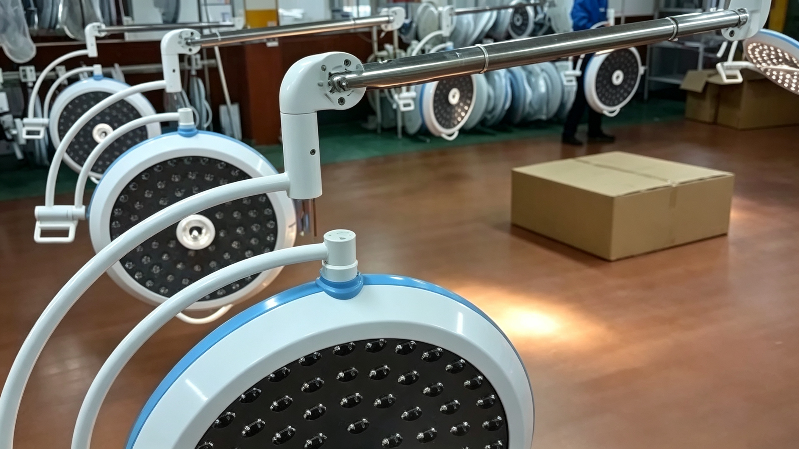
Terminal units reach the patient through three physical routes: wall panels, bedhead/headwall units, and ceiling pendants. In a modern OR, the anesthesia pendant is the primary route — it puts gas, vacuum, AGSS, power, and data directly above the anesthesia machine position and keeps hoses off the floor. This is exactly why pendant selection must happen during pipeline design, not after: the outlet schedule on the pendant must match the schedule of provision, the pendant’s internal pipework and hose tails become part of the pressure-drop calculation, and the ceiling support point must align with the branch pipe routing.
When we supply pendants into a turnkey operating room project, we ask for the MGPS drawings at the same time as the room layout. Three coordination checks prevent 90% of site problems:
- Gas-specific connectors match: the project standard (DISS, BS, DIN, NF, or Ohmeda/Chemetron-type quick connects) must be identical on terminal units, pendant outlets, and the hoses of every anesthesia machine that will ever connect.
- Rotation and reach: the pendant’s sweep must cover the anesthesia position in every table orientation the room will use — check against the actual operating table and its accessory layout, not a generic room centerline.
- Isolation point: each pendant drop should be isolatable (typically at the zone valve serving the room) so a pendant service visit does not shut the suite.
Do not forget the scavenging side. AGSS terminals on pendants need their own routing back to the disposal plant, and their flow-indicating receiving systems need maintenance access that actually exists after the ceiling is closed.

6. Step 5 — Source Equipment and Redundancy
The pipeline is only as reliable as its sources. Under both ISO 7396-1 and NFPA 99 Category 1 requirements, each gas service needs a primary, secondary, and reserve supply philosophy: duplex manifold or liquid supply for oxygen, duplex (often triplex) oil-free compressors for medical air, and duplex vacuum pumps — each unit sized to carry full design load alone. Automatic changeover, with local and master alarm annunciation, must be tested under load at commissioning, not just observed on the control panel.
For operating rooms specifically, plan the emergency reserve manifold (cylinder backup) location and the manual changeover procedure with the people who will perform it at night. A reserve supply that requires three keys and a ladder is a compliance item, not a resilience measure.

7. Testing, Verification, and Handover
Commissioning is where design quality is proven. The standard sequence — mirrored in HTM 02-01 Part A validation/verification and NFPA 99’s installer/performer/verifier split — includes:
- Visual and labeling checks: every pipe run labeled with gas, flow direction, and destination; every valve and terminal identified.
- Pressure and leakage testing: system pressure hold tests, then standing-pressure tests per section. Slow leaks at brazed joints and terminal bodies are the most common failure — and they persist into service if missed. Our article on medical gas outlet leak detection covers the practical field methods for finding and fixing outlet-level leaks after handover.
- Anti-confusion (cross-connection) testing: every terminal tested with a gas analyzer to prove the gas at the outlet is the gas on the label. 100% of terminals. No sampling.
- Flow and pressure-drop verification: worst-case terminals tested at design flow to confirm terminal pressure stays in tolerance.
- Alarm function tests: every pressure switch and annunciator point exercised, with response procedures confirmed with clinical staff.
Experience note: insist on independent verification — a verifier who did not install and does not work for the installer. NFPA 99 requires it; HTM 02-01 requires it; and on three continents I have seen independent verifiers find defects that passed every internal check.
Hand over a complete document pack: as-built drawings, valve schedules, test certificates, gas quality certificates (particulate, moisture, oil, and purity per the pharmacopoeia or standard specified), and the permit-to-work procedure for future modifications. A pipeline without its paperwork will fail its first hospital audit.

Conclusion
Good medical gas pipeline design for operating rooms comes down to sequence and discipline: pick the governing standard, lock the clinical outlet schedule before sizing anything, zone for safe isolation, size pipework from real flow tables with honest diversity, integrate the pendants during design rather than after, and verify independently before the first patient. None of these steps is exotic — but skipping any one of them converts a hidden system into an expensive, visible problem.
If you are scoping a new OR build or a renovation, involve your equipment supplier early. A coordinated package — pipeline, pendants, lights, and tables designed against one set of drawings — is the cheapest insurance in the whole project. Reach out through our contact page if you want our engineering team to review your outlet schedule or pendant gas configuration before you freeze the design.
Frequently Asked Questions
Which standard should govern my OR medical gas pipeline project?
Follow the regulatory framework of the country where the hospital operates: NFPA 99 in North America and much of the Middle East, HTM 02-01 in the UK, and ISO 7396-1-based national standards in most other markets. Decide at project kickoff, write it into the specification, and do not mix philosophies between standards.
How many oxygen outlets does an operating room need?
A typical general OR needs 2–4 oxygen outlets, split between at least two physical locations (for example, the anesthesia pendant and a wall panel). The exact count comes from the schedule of provision agreed with the anesthesia and surgical teams — and always includes a spare for emergency and equipment changes.
What is a zone valve box and where does it go?
A zone (area) valve service unit is a lockable, glass-fronted box containing shut-off valves for each gas serving a defined zone. It must sit in a corridor or staffed area immediately outside the rooms it serves — accessible in an emergency without entering the OR — and be clearly labeled with the gases and rooms it controls.
Why is AGSS piped separately from medical vacuum?
Anesthetic gas scavenging carries waste anesthetic agents that must be exhausted safely, at flow rates and vacuum levels incompatible with the clinical suction system. Connecting AGSS to medical vacuum contaminates the suction plant and fails every governing standard. AGSS always runs to its own dedicated disposal system.
When should pendant selection happen in the design process?
During pipeline design, not after. The pendant’s outlet schedule, internal pipework, hose-tail pressure drop, connector standard, and ceiling support position all affect the MGPS drawings. Selecting the pendant late is one of the most common causes of site change orders on OR projects.
Related reading: Gas Outlet Pressure and Flow Testing After Installation.
You May Also Like...

Patient Flow Design: Pre-Op, Transport and PACU
Operating room patient flow is the sequence from pre-op to the OR to the recovery...

Emergency Department Design: Trauma Bays and Resuscitation
Emergency departments are the most consequential rooms in a hospital to get wrong. Every design...

Maternity OR and Delivery Suite Design
Zoning and transfer corridors in seconds, a dual-duty equipment core, and the newborn readiness details...