


Executive Summary
Peak lux is only half the story. Learn how to measure surgical light illuminance uniformity, read the d50/d10 center-to-edge ratio, and run an IEC 60601-2-41 acceptance test before you sign off.
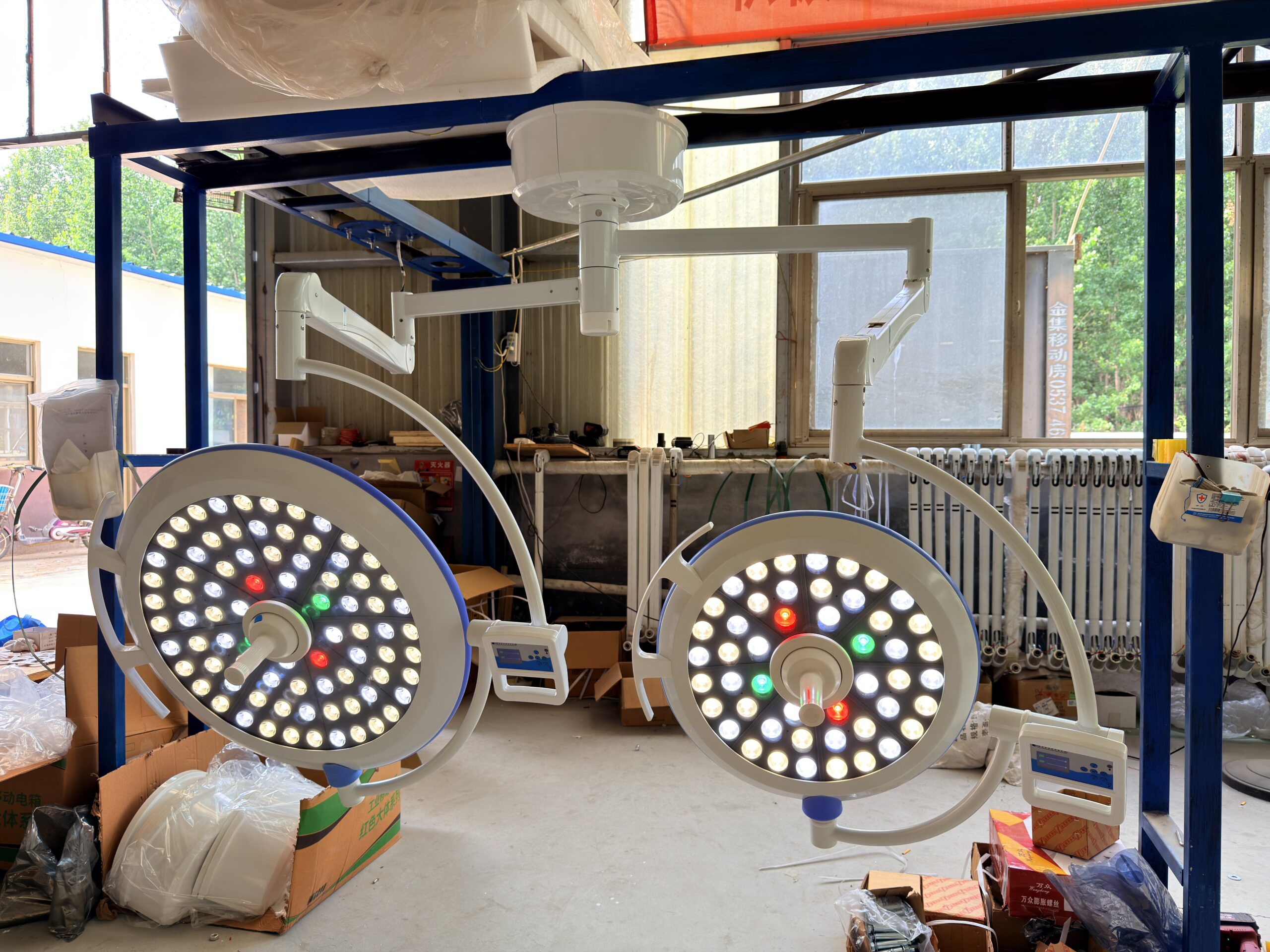
Every surgical light datasheet leads with the same number: peak central illuminance, often 160,000 lux. It is the easiest figure to print and to compare, so it dominates procurement conversations. But after twenty years of watching operating rooms accept, reject, and quietly regret lighting decisions, I can tell you that peak brightness is the least informative number on the sheet. The number that actually predicts whether a surgeon will struggle at depth, whether a scrub nurse will keep repositioning the lighthead, and whether you will field a complaint within six months is surgical light illuminance uniformity — how evenly that brightness is spread across the light field, from the hot center to the working edge.
Here is the painful scenario I have seen repeat from Lagos to Jakarta. A biomedical engineer accepts a brand-new LED surgical luminaire because the central illuminance reads a healthy 130,000 lux on the lux meter. The paperwork passes. Three weeks later, a vascular surgeon complains that the wound edges “fall into shadow” the moment the field is widened for a longer incision. The light is bright in the middle and weak at the rim — the center-to-edge ratio is poor — and nobody measured it at acceptance because nobody knew it had to be measured. That gap between a passing central-illuminance reading and a genuinely usable light field is exactly where your risk lives. Start with a grounded LED surgical light buying guide before you put a lux meter under the lighthead, because the test only catches what the spec already demanded.
This article is a working acceptance-test playbook. It explains the IEC 60601-2-41 metrics that govern uniformity, shows you how to read the d50/d10 center-to-edge ratio like an optical engineer, walks through a repeatable measurement setup, and gives you the red flags that reveal a failing light field before the surgeon notices. Everything is grounded in the current third edition of the standard (IEC 60601-2-41:2021) and in recent peer-reviewed metrology work — no invented numbers, just the thresholds the standard states and the field practices that separate a clean acceptance from a callback.
Why Uniformity Matters More Than Peak Brightness
The human eye adapts to the brightest part of a scene. When a surgeon looks into a wound, their pupils calibrate to the central hot spot. If illuminance then drops sharply toward the edge, the peripheral tissue sinks into relative darkness even where the absolute lux is still adequate. The result is eye strain, repeated repositioning of the lighthead, and a real loss of contrast discrimination at the wound margin — precisely when a surgeon is identifying a vessel plane or a tumor boundary.
This is why two luminaires with identical central illuminance can feel completely different in the same room. One holds a flat, even plateau across a wide field; the other peaks sharply in the middle and tails off. The first has high surgical light illuminance uniformity; the second does not. The takeaway for a buyer is blunt: a high peak-lux figure with a poor uniformity ratio is a worse clinical instrument than a modest peak-lux figure with an even field. Yet peak lux is what almost every tender compares.
In my experience, the lights surgeons complain about are rarely too dim. They are uneven. The center is brilliant and the edge disappears, so the surgeon keeps chasing the field with the handle instead of operating.
Uniformity also interacts with two areas you already care about. Color rendering degrades unevenly across a poorly mixed LED field, so the rim of the spot can shift in tone — a problem we cover in our piece on surgical light color rendering degradation. And a light driven to maximum output to compensate for a weak edge ages its LED modules faster and burns more energy, feeding the total-cost math in our surgical light maintenance and TCO analysis. Uniformity is not a luxury spec line.
The IEC 60601-2-41 Metrics You Actually Need to Verify
The current edition, IEC 60601-2-41:2021 (Edition 3, published September 2021, stability date 2026), is the particular standard for the basic safety and essential performance of surgical luminaires, replacing the 2009 second edition and its 2013 amendment. Edition 3 introduced changes that matter for acceptance testing: a manufacturer-defined reference distance (DRef) and maximum illuminance distance (DMI), a Duv chromaticity requirement replacing the old (x,y) region, and tighter photobiological-hazard limits. For uniformity work, the definitions to internalize are the central illuminance and the two light-field diameters.
Central illuminance (EC,Ref) is the illuminance at the center of the light field, measured at the reference distance. The standard sets a floor for surgical luminaires of 40 klx (40,000 lux) and a ceiling of 160 klx (160,000 lux) on the vertical axis. That ceiling exists for patient safety — excessive irradiance on exposed tissue raises thermal risk. A manufacturer cannot simply chase the highest number; the design must sit inside a defined band while delivering an even field.
Light-field diameter d10 is the diameter of the area, on a horizontal measurement plane, where illuminance has fallen to 10% of the central value. Light-field diameter d50 is the diameter where it has fallen to 50%. The uniformity requirement is a ratio between the two: d50 must be at least 0.5 × d10. The closer d50 is to d10, the more homogeneous the field and the better defined the working area. That single inequality is the heart of surgical light illuminance uniformity, and the most useful number to record at acceptance.
| Parameter | Symbol | IEC 60601-2-41:2021 Requirement (Surgical) | What It Tells You at Acceptance |
|---|---|---|---|
| Central illuminance (min) | EC,Ref | ≥ 40 klx | Bright enough for deep-cavity work at the reference distance |
| Maximum central illuminance | EC | ≤ 160 klx | Patient thermal-safety ceiling; not exceeded on the vertical axis |
| Light-field uniformity ratio | d50 / d10 | d50 ≥ 0.5 × d10 | Evenness of the field; closer to 1.0 means a flatter, more usable spot |
| Total irradiance | — | ≤ 700 W/m² | Heat load on tissue; watch for overlapping fields |
| Color rendering index | Ra | ≥ 85 | Tissue color fidelity; should hold across the field, not just center |
| Correlated color temperature | CCT | 3,000 K – 6,700 K (Duv within ±0.02) | Neutral, color-neutral white that supports diagnosis |
| Single-failure recovery | — | Restore ≥ 40 klx within 1 s (system) | Essential performance is maintained if part of the system fails |
A subtle but important point from Edition 3: the manufacturer may specify the reference distance DRef at which performance is declared, and a separate maximum illuminance distance (DMI) is defined. You therefore cannot blindly compare two datasheets unless both declare values at comparable distances. Always record the distance at which you take your acceptance reading — a 130,000 lux figure is meaningless without it.
Reading the Center-to-Edge Ratio: d50/d10 Like an Engineer
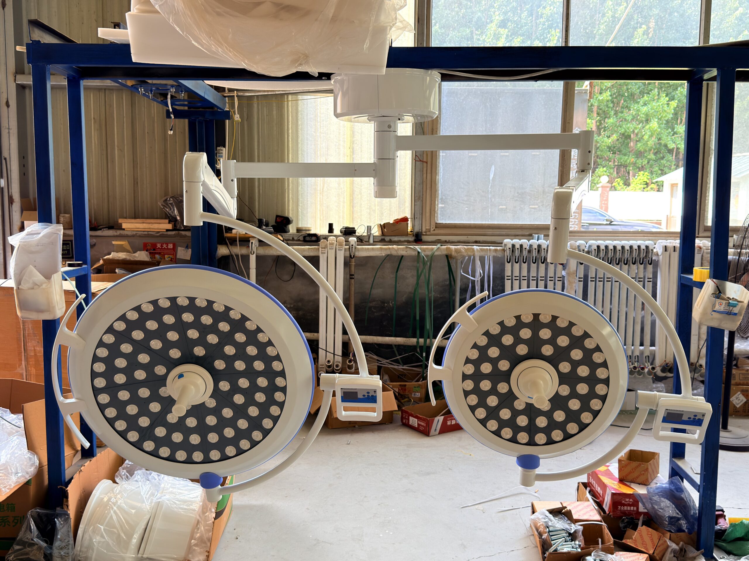
Think of the light field as a hill. The peak is the central illuminance. The d50 contour is where the hill has dropped to half its peak height; the d10 contour is where it has dropped to a tenth. A steep, narrow hill has a small d50 relative to its d10 — the light falls away fast and the bright core is small. A broad, flat-topped hill has a d50 nearly as large as its d10 — the light stays strong well toward the edge. The d50/d10 ratio describes the shape of that hill.
The standard’s minimum of d50 ≥ 0.5 × d10 is the floor, not the target. A ratio of 0.5 means the half-brightness zone is half the width of the tenth-brightness zone — acceptably even but visibly peaked. Premium luminaires push toward 0.7 or higher, producing a flat plateau surgeons describe as “the whole field just stays bright.” When comparing bids, ask each manufacturer to state the measured d50 and d10 in millimetres at the declared reference distance, then compute the ratio yourself. Do not accept a marketing phrase like “excellent homogeneity” without the two underlying diameters.
- Ratio around 0.5–0.55: Meets the standard, but the field is noticeably peaked. Acceptable for general surgery; surgeons doing wide-field work may reposition frequently.
- Ratio around 0.6–0.7: A genuinely even field. This is the sweet spot for most tertiary and teaching hospitals where long procedures and camera work are routine.
- Ratio above 0.7: Very flat, well-engineered optics. Often found on higher-end heads with carefully mixed multi-channel LED arrays and precision collimation.
- Ratio below 0.5: Fails the standard. The center is bright but the working edge collapses. Reject or require remediation before sign-off.
Recent peer-reviewed work adds nuance. A 2022 study in Lighting Research & Technology on obstructed LED surgical lighting found that the d50/d10 ratio was not strongly affected by an obstruction, but the shape of the spot deformed visibly on some products; the authors proposed an “illuminance attenuation dispersion rate” as an extra discriminator. The lesson: a single ratio is necessary but not sufficient. Also check whether the spot stays circular and symmetric, or warps into a lopsided blob when the head is angled — a warped field concentrates brightness on one side and starves the other in a way no single number captures.
Record the d50/d10 ratio at acceptance, but also photograph the light field on a white card. A symmetric, near-circular spot with soft, even falloff is worth more than a slightly better ratio on a lopsided, deformed field.
Setting Up the Measurement: Distance, Field Diameter, and the Lux Meter
You do not need a national metrology lab to run a credible acceptance test, but you do need a disciplined setup. The instrument is a calibrated lux meter with a cosine-corrected photometer head. Position the lighthead so its beam axis is perpendicular to a horizontal measurement plane — a clean white board or non-reflective matte surface works. The measurement distance is the reference distance DRef declared by the manufacturer; if it specifies 1,000 mm, measure at 1,000 mm. A 2024 biomedical-engineering study at the University of São Paulo positioned a photometer centrally at 1 m from the lowest part of the luminaire and sampled along vertical and horizontal axes at fine intervals — a sound template you can adapt.
Extracting d10 and d50 is straightforward once the geometry is fixed. First find the point of maximum illuminance — the center of the field — and record it as EC,Ref. Then move the photometer head radially outward along at least two perpendicular axes. Note the radial distance where the reading drops to 50% of EC,Ref; twice that radius is d50. Continue to 10%; twice that radius is d10. Average the diameters from the axes you measured and compute d50/d10.
- Warm up the light. Run the luminaire at the test intensity for several minutes before measuring so output and driver stabilize. Cold readings drift.
- Control ambient light. Room lighting adds a constant offset that inflates the edge values and flatters the ratio. Dim or switch it off, or subtract a measured baseline.
- Set the intensity deliberately. Decide whether you test at maximum output or a nominal clinical level, and state it. The ratio can shift slightly with dimming on some drivers.
- Keep the head square. Tilting changes the projected field shape. Keep the beam perpendicular for the baseline number; test angled performance separately as a shadow-dilution check.
- Log the distance. Write DRef on the record. A lux value without its distance is not comparable to anything.
A Step-by-Step Acceptance Test Protocol
Here is the field protocol I recommend writing into your commissioning checklist. It takes roughly twenty to thirty minutes per lighthead and produces a one-page record you can file against the asset and defend in an audit — non-negotiable before the room goes live.
Step 1 — Verify documentation first. Before you touch the meter, confirm the luminaire’s declared values: central illuminance at DRef, d10, d50, color temperature, Ra, and the test-report reference. Cross-check the model and serial against the delivery note. If the manufacturer cannot produce a declared DRef or a measured d50/d10, that is a documentation failure worth flagging before any physical test.
Step 2 — Establish geometry and warm up. Set the lighthead at the declared reference distance above the measurement plane, beam perpendicular. Run it at the chosen test intensity for several minutes. Confirm the lux meter is calibrated (a current calibration sticker should be on the instrument) and zero it against ambient light.
Step 3 — Measure central illuminance. Locate the maximum point and record EC,Ref. Confirm it sits inside the 40–160 klx band. A reading below 40 klx at the declared distance is an essential-performance failure; a reading above 160 klx on the vertical axis is a safety concern. Either way, stop and document.
Step 4 — Map the field and extract d50 and d10. Traverse radially along two perpendicular axes, recording the radial distances where the reading crosses 50% and 10% of EC,Ref. Compute the diameters and the d50/d10 ratio. Confirm d50 ≥ 0.5 × d10.
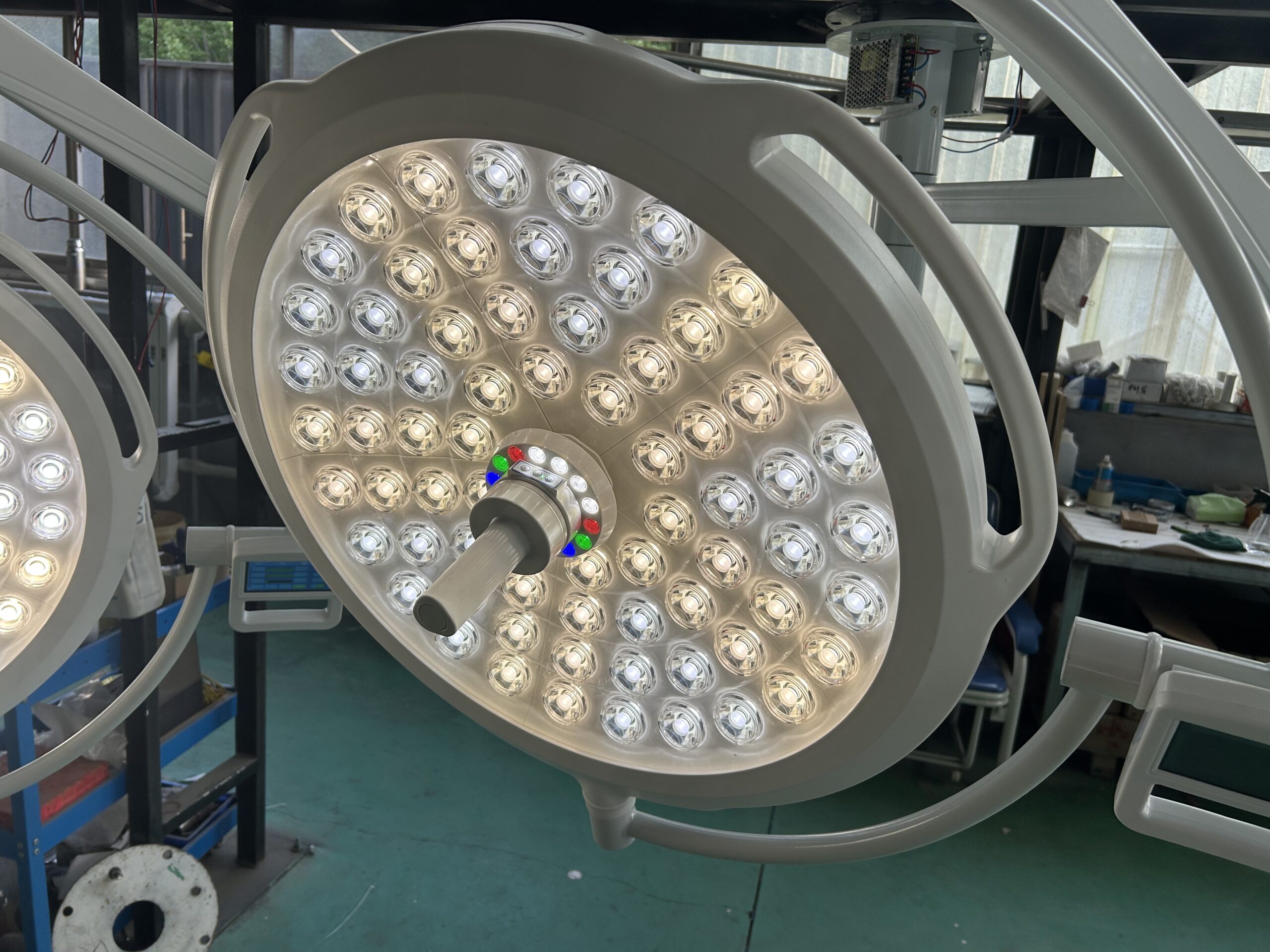
Step 5 — Check the spot shape and the depth of illumination. Photograph the field on a white card and confirm it is symmetric. If your protocol includes it, measure the depth of illumination (the L1 + L2 distances along the beam axis where illuminance falls to 60% of EC,Ref) to confirm the column of light reaches into a cavity. A 2026 on-site metrology study from a Chongqing institute formalized this kind of closed-loop “measure, judge, adjust” routine — validation that a structured field protocol is both practical and defensible.
Step 6 — Repeat per head and per mode. For a twin-head system, test each lighthead independently, then verify behavior with both heads overlapping (watch the total-irradiance ceiling of 700 W/m² where fields overlap). If the luminaire has selectable field-size or deep-cavity modes, repeat the uniformity check in each mode the surgeon will actually use.
Red Flags: What a Failing Light Field Is Telling You
A uniformity failure is rarely random; it is a signature. Learning to read it tells you whether you face a fixable setup issue or a fundamental optical-design problem you should reject. Here are the patterns I watch for.
- Sharp central peak, fast falloff (low d50/d10): Optics concentrating light into a narrow core, common on lower-cost heads with simple lens arrays. The surgeon chases the field. This is a design characteristic — every unit of that model behaves the same.
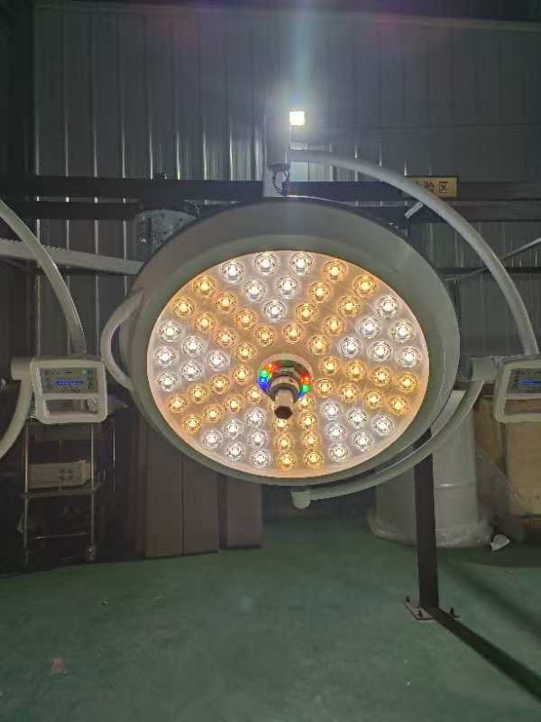
- Lopsided or comma-shaped spot: Misaligned optics, a shifted LED board, or a damaged reflector. If it appears on one unit but not its twin, suspect assembly or transport damage. A strong candidate for warranty replacement.
- Color shift toward the rim: Center neutral, edge greenish or magenta. Poor angular color mixing across the LED channels, often correlating with low off-axis Ra. It frustrates tissue discrimination at the wound margin.
- Central illuminance below 40 klx at DRef: An essential-performance shortfall. Confirm distance and intensity first; if it holds, the unit does not meet the standard for surgical use.
- Visible flicker or output drift during warm-up: Driver instability. It undermines every reading and signals a reliability risk that surfaces later as maintenance cost.
When you find a failure, distinguish setup error from hardware fault before you reject. Re-square the head, re-confirm the distance, and re-measure. If the anomaly persists on a correctly set-up unit, document it with the photograph, the measured diameters, and the computed ratio, and raise it against the supplier with the record attached. A supplier that stands behind its optics responds to data; one that argues with a calibrated lux meter tells you something about the relationship ahead.
Building Uniformity Into the Procurement Spec
The cheapest time to enforce surgical light illuminance uniformity is before the purchase order, not at the loading dock. If your tender only compares peak lux, you will receive bids optimized for peak lux. Write the uniformity requirement into the specification so suppliers compete on the metric that actually drives clinical satisfaction.
- State the ratio, not a slogan. Require a declared d50/d10 of at least 0.5 (the IEC floor) and, for main operating rooms, a target of 0.6 or higher. Ask bidders for measured d10 and d50 in millimetres at a stated DRef.
- Demand a test report, not a brochure claim. Require an end-of-line or type-test report referencing IEC 60601-2-41:2021, with central-illuminance and light-field-diameter values traceable to a calibrated instrument.
- Reserve the right to verify on delivery. Make acceptance testing a contractual milestone. A supplier who knows you will measure ships consistent units.
- Specify the whole optical package. Uniformity travels with color rendering, color-temperature stability, and shadow dilution. Specify them together so a bidder cannot win on one number and fail on the others.
If you are equipping a whole department rather than a single room, fold the lighting acceptance into a broader commissioning plan. Our guide to turnkey operating room solutions shows how lighting, tables, pendants, and gas systems are validated together so no subsystem is signed off in isolation. To translate a specification into a shortlist, browse the full Sanyang Medical surgical lights range to see how declared d10/d50 values, color rendering, and field-size modes are presented for each model. For a sample test report or uniformity datasheet for a specific configuration, contact our engineering team.
Conclusion
Peak central illuminance gets the headlines, but surgical light illuminance uniformity is what determines whether a light field actually supports the surgeon across the whole wound. IEC 60601-2-41:2021 gives you a precise, testable language for it: a central-illuminance band of 40–160 klx, the two light-field diameters d10 and d50, and the rule that d50 must be at least half of d10. The closer that ratio approaches 1.0, the more usable the field.
The acceptance test is not difficult, but it must be disciplined: fix the reference distance, control ambient light, warm up the luminaire, measure the center, traverse the axes to extract d50 and d10, compute the ratio, and check the spot shape. Build that protocol into your commissioning checklist and your tender, and you stop accepting lights that look bright on paper but disappoint in the cavity. The hospitals that get this right are not the ones with the biggest budgets; they are the ones that measure.
Frequently Asked Questions
What is a good d50/d10 ratio for a surgical light?
The IEC 60601-2-41:2021 minimum is d50 ≥ 0.5 × d10, so 0.5 is the compliance floor. In practice, 0.6 to 0.7 indicates a genuinely even field suitable for long procedures and camera-assisted surgery, while anything above 0.7 reflects very flat, well-engineered optics. Below 0.5, the field fails the standard and the working edge feels dim relative to center.
At what distance should I measure central illuminance during acceptance?
Measure at the reference distance DRef declared by the manufacturer, because Edition 3 lets the manufacturer specify the distance at which performance values are stated. Many post-market studies use 1 m from the lowest part of the luminaire as a practical reference. Always record the distance on your report — a lux value without its measurement distance cannot be compared against the datasheet.
Can I test surgical light illuminance uniformity with a hand-held lux meter?
Yes. A calibrated, cosine-corrected lux meter is sufficient to measure central illuminance and to traverse the field for d50 and d10. The key is a controlled setup: square the beam to the measurement plane, dim or subtract ambient light, warm up the luminaire, and sample along at least two perpendicular axes. A national-lab-grade rig is not required for a credible, defensible reading.
Why does my light feel dim at the edge even though the center reads high?
That is the classic symptom of a peaked field with a low d50/d10 ratio. The eye adapts to the bright center, so the faster falloff toward the rim reads as relative darkness even when the absolute lux is adequate. It usually points to optics that concentrate light into a narrow core rather than a flat plateau. Confirm it by measuring d50 and d10; if the ratio is near or below 0.5, the field is genuinely uneven.
Does uniformity testing replace shadow-dilution testing?
No. They measure different things. Uniformity (d50/d10) describes how even the unobstructed field is, while shadow dilution describes how much usable light remains when the surgeon’s head or instruments block part of the beam, tested with standardized masks and a simulated cavity. A complete acceptance protocol checks both, because a light can have an even open field yet perform poorly once obstructed.
You May Also Like...

Surgical Light Control Systems Explained: Touch Panels, Wall Controls, Sterile Handles and Integrated OR Control
A practical guide to the five surgical light control systems - touch panels, wall control...
Surgical Light Tender Specifications: The Complete Procurement Checklist
A practical checklist of the photometric parameters, certifications, and evaluation steps that belong in every...

Surgical Light Installation Requirements: Ceiling Load, Height and Coordination Guide
A practical guide to surgical light installation requirements: ceiling load and moment, clear height, arm...