
Executive Summary
How to choose a C-arm compatible operating table: radiolucent carbon fiber tops, base clearance, tabletop travel, load trade-offs, and IEC 60601-2-46 compliance — a practical buying guide.
Every procurement team I’ve worked with in imaging-heavy ORs has the same story. They bought an “operating table” that looked great on the spec sheet — 250 kg capacity, electric height adjustment, full accessory rail set — and then the C-arm arrived. The base collided with the C-arm’s orbital rotation. The tabletop attenuated the beam so badly that the radiographer had to crank up the dose. The surgeons ended up rolling patients onto a stretcher for every intra-op image. The table wasn’t wrong for surgery; it was wrong for imaging. And in orthopedics, trauma, spine, urology, pain management, and vascular work, imaging is the surgery.
A true C-arm compatible operating table is engineered around the fluoroscopy workflow first and the surgical workflow second. That means a radiolucent tabletop, a base geometry that stays out of the C-arm’s path, enough longitudinal travel to cover head-to-toe imaging, and controls the radiographer can use without breaking the sterile field. In our factory’s operating table production line, imaging-compatible builds have grown from a niche request to roughly a third of OEM orders over the past few years — driven by hybrid OR construction and the spread of mobile C-arms into mid-tier hospitals.
This guide walks through the seven decisions that determine whether a table will actually work with your C-arm — not in the catalog, but on a Tuesday morning with a trauma case on the table. I’ll cover radiolucency metrics, base design, tabletop travel, load capacity trade-offs, positioning accessories, electrical and regulatory compliance, and the acceptance tests you should run before signing off.
1. Understand What “C-Arm Compatible” Actually Means
There is no certification called “C-arm compatible.” It’s a marketing term. Two tables can both carry the label and perform completely differently under a fluoroscopy unit. What matters are four measurable properties:
- Radiolucency of the tabletop — how much the panel attenuates the X-ray beam, usually expressed as millimeters of aluminum equivalent (mm Al eq). Lower is better.
- Metal-free imaging zone — the length of tabletop through which the beam can pass without crossing a metal support rail, hinge, or actuator.
- Base geometry — whether the column and base allow the C-arm to achieve lateral, oblique, and over-table projections without collision.
- Tabletop travel — longitudinal float or shift that lets you scan from skull to feet without repositioning the patient or the C-arm gantry.
The safety baseline is IEC 60601-2-46, the particular standard for basic safety and essential performance of operating tables (current edition: IEC 60601-2-46:2023, which realigned the standard structurally with IEC 60601-1). Any table you shortlist should have test reports against this edition, not just a generic CE mark. For imaging use specifically, IEC 60601-2-54 covers patient-supporting systems of X-ray equipment — relevant if the table is sold as an integrated imaging table rather than a surgical table used with a mobile C-arm.
Rule of thumb from the field: if the vendor can’t state the tabletop’s attenuation in mm Al equivalent, they haven’t tested it. Ask for the number before you ask for a price.
2. Radiolucency: The Tabletop Material Decision
The tabletop material is the single biggest determinant of image quality and radiation dose. A standard phenolic or steel-framed top forces the radiographer to increase kVp and mAs to punch through, which raises dose for both patient and staff and degrades contrast. Carbon fiber changed this equation. Modern carbon fiber composite tops attenuate the beam only marginally more than air-equivalent padding, which is why virtually every serious imaging table — from Getinge’s Maquet carbon fiber tops to dedicated pain-management tables — uses carbon fiber for the imaging zone.
When comparing specs, look for three things:
- Attenuation value with pad included. Vendors love quoting the bare panel. A 50 mm memory foam pad adds attenuation; the honest number is panel + pad at a stated beam energy (typically 100 kVp).
- Edge and rail construction. Aluminum accessory rails under the imaging zone will show up in lateral shots. Better designs recess the rails below the beam path or use composite rails in the imaging section.
- 360° radiolucent length. High-end carbon fiber tops quote radiolucent lengths up to roughly 2,000 mm with overhang beyond that — enough for full-spine and vascular runoff studies. General surgical tables with a carbon fiber section typically offer much less; check whether it’s enough for your longest typical procedure.
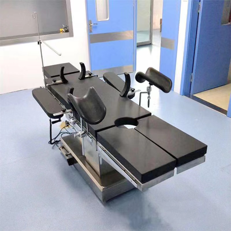
One practical note: radiolucent pads wear faster than standard pads, and a compressed, creased pad creates imaging artifacts and pressure injuries at the same time. Budget for pad replacement as a consumable, and inspect pads at every preventive maintenance visit. (Our guide on operating table pad damage covers inspection criteria in detail.)
3. Base Geometry: Where C-Arms Actually Collide
Ask any radiographer what frustrates them most and they’ll say the base, not the top. A C-arm needs to swing through its orbital and wig-wag range around the patient. Wide pedestal bases, side columns, and under-table actuator housings block that swing — especially for lateral lumbar spine shots and pelvic obliques, where the image intensifier ends up low and close to the table edge.
Three base designs dominate imaging-compatible tables:
- Cantilevered (offset column) bases — the column sits at one end, leaving a long metal-free overhang. Best for pain management, vascular, and cardiac work where the C-arm moves along the full body length.
- Slim central columns with low-profile bases — a compact base (often T-shaped or offset-foot) that the C-arm’s low end can straddle. The standard solution for orthopedic and general imaging tables.
- Split-leg or articulating bases — legs that open or retract to admit the C-arm from the foot end for pelvic and hip work.
Before purchase, get the base footprint drawing and overlay it against your C-arm’s technical manual — every C-arm manufacturer publishes minimum clearance diagrams. Pay attention to the lowest height of the image intensifier relative to the floor, and the table’s minimum height. A table that only goes down to 750 mm may leave the intensifier unable to get under the top for under-table-tube geometry.
I’ve seen a hospital reject a container-load shipment because the table base was 40 mm too wide for their C-arm’s swing arc. Clearance checks cost nothing. Returns cost everything.
4. Tabletop Travel and the Imaging Zone
For full-body imaging — spinal instrumentation, vascular runoff, trauma surveys — the patient must move relative to the C-arm, or the C-arm relative to the patient, without repositioning. Two mechanisms deliver this:
Longitudinal shift (the whole tabletop slides on the column, typically 300–600 mm) is the surgical-table solution. It’s simple, robust, and enough for most orthopedic work when combined with a metal-free overhang. Floating tabletops (free or motorized float in X and Y, sometimes with isocentric lateral roll) are the dedicated imaging-table solution — cardiovascular float tops commonly offer around 35 inches of head-to-toe travel and radiolucent areas of 70+ inches, with lateral roll that keeps the anatomy centered on the image axis.
Match the travel to your case mix. If your OR does mostly fracture fixation with a mobile C-arm, a general surgical table with 300+ mm of longitudinal shift, a carbon fiber section, and a slim base will serve you well and cost far less than a dedicated float-top angio table. If you’re planning a hybrid room with fixed imaging, the decision logic changes entirely — our turnkey operating room team handles the table-imaging-layout integration as one package for exactly this reason.

5. Load Capacity vs. Radiolucency: The Honest Trade-Off
Carbon fiber tops are strong, but physics is unforgiving: a long, thin, cantilevered radiolucent top cannot carry the same static load as a short steel-framed top. Dedicated imaging tables often rate 225–250 kg (about 500 lb) in the centered position and significantly less with the top fully extended. General surgical tables with carbon fiber sections may rate higher centrally but restrict loads in the radiolucent zone.
Handle this in three steps. First, define your real bariatric requirement — what percentage of your case mix actually exceeds 180 kg, and can those cases be scheduled on a non-imaging table? Second, check the load rating in every articulated position, not just flat: Trendelenburg, lateral tilt, and full longitudinal extension each reduce permissible load. Third, verify the rating includes the accessory weight — traction frames, arm boards, and leg holders add up fast. IEC 60601-2-46 requires stability testing under defined load conditions, so ask for the actual test report, not just the marketing number.

6. Drivetrain, Controls, and Electrical Safety in an Imaging Environment
Electric actuation has effectively won this segment — precision electric actuators produce smooth, artifact-free motion, and unlike hydraulic systems there’s no oil to leak onto a carbon fiber panel (hydraulic fluid contamination can permanently cloud a radiolucent top). If you’re still weighing the two technologies, our electric vs. hydraulic operating table comparison goes deep on lifecycle costs.
For imaging suites specifically, check these electrical details:
- Battery backup with mains operation — the table should run full-function on battery for cord-free imaging, but never lock you out when the battery degrades.
- EMC compliance (IEC 60601-1-2) — the table’s motors and controls must not interfere with the imaging chain, and vice versa.
- Hand and foot controls — the radiographer often needs to move the table while standing at the C-arm console; a wired or wireless hand pendant plus foot switch is standard on serious imaging tables.
- Equipotential grounding — imaging rooms are electrically dense environments; verify the grounding terminal and test it at commissioning.

7. Positioning Accessories and the Hidden Imaging Blockers
Even a perfectly radiolucent table can be sabotaged by its accessories. Metal arm boards, steel traction frame components, and clamp-on leg holders all cast shadows in the beam path. When you configure the table, walk through your top ten procedures and ask where every accessory sits relative to the imaging zone. For orthopedic trauma, a traction frame with carbon fiber spars costs more than the steel version but removes the single most common artifact source in hip pinning cases. For lateral spine work, check that the kidney bridge mechanism — if the table has one — doesn’t rise into the beam when elevated.
Also confirm rail compatibility before mixing brands. Accessory rail profiles vary (common metric and imperial standards exist side by side), and an adapter clamp sitting proud of the rail can intrude into the C-arm’s swing envelope just as surely as the table base can. We keep a rail-and-clamp compatibility matrix for our tables precisely because this question arrives after delivery in about one project in five.
8. Regulatory and Procurement Checklist
For tender submissions and import clearance, assemble the documentation before you negotiate price. Under the EU MDR (Regulation 2017/745), operating tables are typically Class I or IIa depending on function, and the technical file must reference the applicable IEC 60601 series standards. The manufacturer should hold ISO 13485 certification for their quality management system — verify the certificate scope actually covers operating tables, not just “medical devices” generically.
| Checkpoint | What to Ask For | Red Flag |
|---|---|---|
| Radiolucency | Attenuation in mm Al eq, with pad, at stated kVp | “Highly radiolucent” with no number |
| Imaging zone | Dimensioned drawing of metal-free length | Rails/hinges inside the imaging zone |
| Base clearance | Base footprint + min/max height drawings | No dimensional drawings available |
| Safety standard | IEC 60601-2-46:2023 test report | CE mark with no underlying test data |
| QMS | ISO 13485 certificate covering OT tables | Certificate scope mismatch |
| Load rating | Rated load in each articulated position | Single “max load” figure only |
| Acceptance test | On-site trial with your actual C-arm | Vendor refuses a live imaging demo |
If you’re a distributor building a private-label imaging table line, this is also the point to lock the specification with your OEM partner — tabletop material, radiolucent length, base variant, and control set all affect tooling and certification scope. Our OEM/ODM localization service typically starts imaging-table projects with exactly this checklist, then runs CE/IEC test samples through a notified body before mass production.
The cheapest imaging table is the one that passes acceptance testing the first time. Every ambiguity you leave in the tender spec becomes a change order later.
Conclusion
Choosing a C-arm compatible operating table is really four decisions in one: how much radiolucency you need, what base geometry fits your imaging equipment, how much tabletop travel your longest procedures demand, and what load capacity you’re genuinely willing to trade for imaging access. Get those four right, verify them against IEC 60601-2-46 test data and a live trial with your own C-arm, and the rest is procurement hygiene — ISO 13485, MDR documentation, spare pads, and a service plan.
If you’re speccing a hybrid OR, a trauma room, or a private-label imaging table line, talk to us early — the layout, table, and imaging decisions are far cheaper to make together than separately. Contact our engineering team with your C-arm model and case mix, and we’ll come back with a matched table configuration and dimensional clearance check.
Frequently Asked Questions
What makes an operating table C-arm compatible?
Four properties: a radiolucent tabletop (low X-ray attenuation, usually carbon fiber), a metal-free imaging zone long enough for your procedures, a base design that doesn’t block the C-arm’s orbital swing, and sufficient tabletop travel to image without repositioning the patient. “C-arm compatible” has no formal certification — always verify with dimensional drawings and an on-site imaging trial.
How much tabletop travel do I need for full-spine or vascular imaging?
For full-body imaging with a fixed or mobile C-arm, dedicated imaging tables offer roughly 900 mm (about 35 inches) or more of head-to-toe travel, with radiolucent areas approaching 1,800–2,000 mm on high-end carbon fiber tops. General surgical tables with 300–600 mm of longitudinal shift cover most orthopedic cases when combined with a metal-free overhang.
Is carbon fiber always the right tabletop material?
For any procedure involving intraoperative fluoroscopy, yes — nothing else matches its strength-to-attenuation ratio. For rooms where imaging is rare, a standard top with a removable radiolucent extension can be more economical. Also remember that radiolucent pads wear faster and need scheduled replacement to avoid image artifacts and pressure injuries.
What load capacity should a C-arm table support?
Most dedicated imaging tables rate around 225–250 kg centered, less when articulated or fully extended. Define your real bariatric case percentage first, then check the rated load in every position you actually use — Trendelenburg, tilt, and full extension — including accessory weight. Demand the IEC 60601-2-46 stability test report rather than a single headline number.
Which standards apply to C-arm compatible operating tables?
The core standard is IEC 60601-2-46:2023 (operating table safety and essential performance), with IEC 60601-1-2 for electromagnetic compatibility. Integrated imaging patient supports may also reference IEC 60601-2-54. For EU market access, the table falls under MDR 2017/745, and the manufacturer’s ISO 13485 quality system certificate should explicitly cover operating tables.
You May Also Like...

Bariatric OR Package: Table, Bed and Trolley Coordination
A bariatric OR package coordinates the operating table, the patient bed and the trolley for...

Lumen vs Lux: What These Surgical Light Units Mean
Lumen and lux are not the same thing. Lumen measures the total light a fixture...

Emergency Department Equipment for Trauma, Resuscitation and Triage
An emergency department is built around speed, and its equipment has to be ready the...