

Executive Summary
A practical engineering guide to medical pendant electrical integration: strong/weak current separation, socket count and standards, network and data interfaces, equipotential bonding to 0.2 ohm, internal wiring, and a factory acceptance checklist for procurement teams.
Most buyers specify a medical pendant by counting gas outlets and arm length, then treat the electrical side as an afterthought. That is exactly backwards. In my years commissioning operating rooms and intensive care units, the pendant failures that actually stop clinical work are rarely mechanical — they are electrical and data faults. A tripped socket circuit during a case, a network port that was never wired, a bonding point that fails its 0.2 Ω test the week before handover. The hardware that carries power, data, and protective earth into the patient environment is the highest-risk part of the whole medical pendant specification, and the part most often underspecified at tender stage.
For the electrical and data integration work inside a retrofit, see our medical pendant retrofit guide.
The problem is that a pendant sits at the intersection of three trades that rarely coordinate: medical gas, structural mounting, and electrical installation. The gas engineer counts outlets, the structural engineer checks the ceiling load, and the electrical contractor expects someone else to have defined the socket schedule, data drops, and bonding scheme. When those decisions default to the factory’s “standard configuration,” you inherit a layout that may be perfectly standard — and perfectly wrong for your room. Getting medical pendant electrical integration right means deciding, in writing, how strong and weak current are separated, how many sockets of which standard you need, which data interfaces the clinical team uses, and how the bonding will be tested before the room goes live.
For teams working through the same decision, see our how AI is changing OR equipment.
This guide walks through the electrical and data integration of ceiling pendants the way every procurement team should approach it: as a defined engineering scope with acceptance criteria, not a line item.
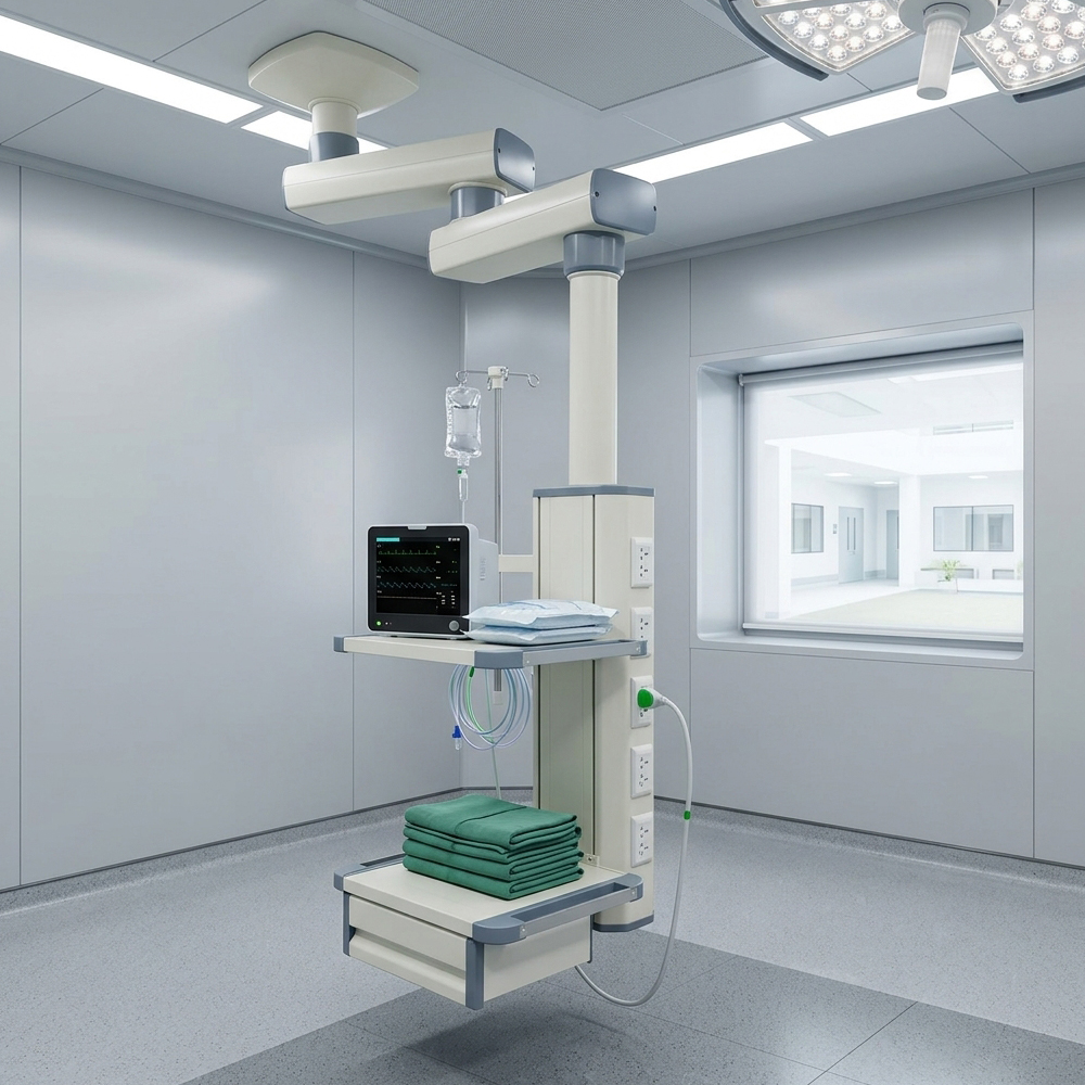
Why Electrical and Data Integration Is the Real Risk on a Pendant
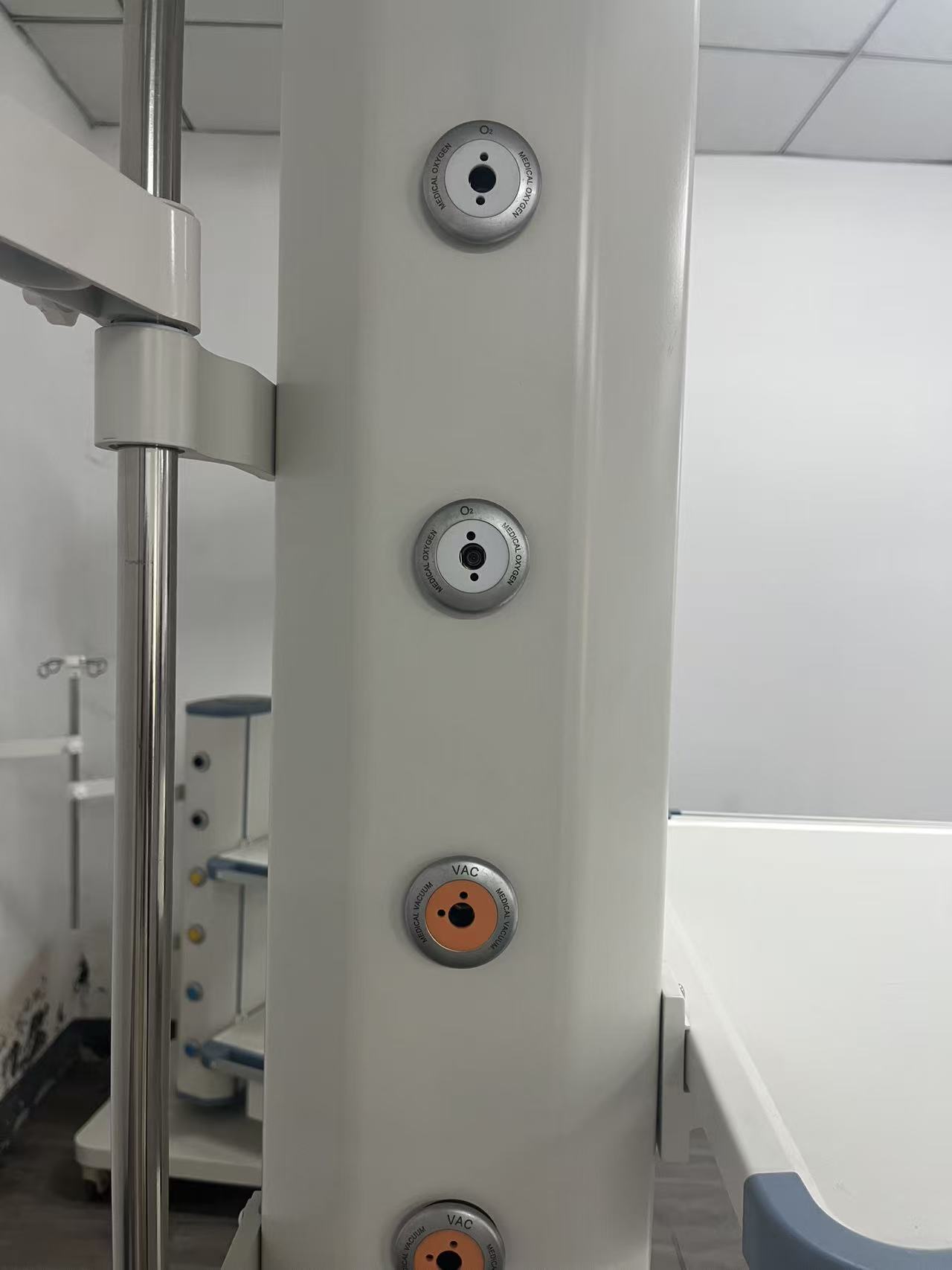
A ceiling pendant is, functionally, a service column hung from the slab, delivering medical gases, mains power, protective earth, and increasingly data and network connectivity to a moving zone around the patient or table. The mechanical arm gets the attention because it is visible, but the electrical package determines whether the devices on that arm run safely and communicate with the rest of the hospital.
Consider what plugs into a typical theatre or ICU pendant: anaesthetic machines, monitors, infusion pumps, ventilators, electrosurgical units, warming devices, sometimes imaging equipment — plus nurse-call and telemedicine on an ICU bridge. Every load draws current, generates heat, and connects to the patient environment. That is why wiring regulations treat operating theatres as Group 2 medical locations, the highest-risk category, where the patient may be connected to applied parts used for life support or monitoring.
A pendant that passes a gas leak test can still fail an electrical safety audit. Treat the electrical and data scope as a first-class deliverable, with its own drawings and acceptance tests, not a footnote to the gas schedule.
The standards here are not optional. IEC 60364-7-710 (and regional adoptions such as HD 60364-7-710 and BS 7671 Section 710) governs electrical installations in medical locations; the 2026 BS 7671 update (Amendment 4) rewrote Section 710 and tightened the documentation requirements for supplementary equipotential bonding. IEC 60601-1 governs the equipment that plugs in. The pendant is the bridge between those regimes, and if its wiring, socket ratings, and bonding do not match, the whole chain of compliance is weakened.
Strong and Weak Current Separation: The Foundation of Safe Integration
The single most important design rule in medical pendant electrical integration is separating strong current (mains power, typically 220–240 V AC) from weak current (data, network, signal, and extra-low-voltage circuits). Reputable manufacturers state this explicitly: gas pipeline, power supply, and communication lines should be arranged separately so they do not interfere. This is not a marketing claim — it is a safety and electromagnetic-compatibility requirement.
Why does separation matter? First, safety: mains conductors carrying fault current must never contact a data or signal line running to a patient-connected device, or a hazardous voltage can appear on a circuit the clinical team assumes is safe. Second, electromagnetic compatibility: power cables feeding switching loads induce noise onto unshielded data cables, causing intermittent monitor dropouts no one can reproduce on demand.
- Physically divided channels: Specify a pendant whose arm and column have separate internal ducts for power and for data/signal. Where a single duct is unavoidable, demand a dividing partition or segregated trunking rather than a shared bundle.
- Gas-electric isolation: The internal layout should also isolate power lines from gas lines. Manufacturers cite this as a fire-prevention measure; it also keeps heat from power conductors away from gas terminals.
- Crossing at right angles: Where power and data paths must cross inside the structure, they should cross at 90 degrees rather than run parallel, minimizing inductive coupling.
- Shielded data cabling: For network and signal lines routed near power, use screened (shielded) cable with the shield correctly terminated, and keep the separation distance the manufacturer recommends.
At tender stage, do not accept “cables are separated” as a yes/no answer. Ask for a cross-section drawing of the arm showing the power duct, data duct, and gas channels, and confirm which segregation standard is applied. This is the same discipline you would bring to medical pendant cable management at the bedside — except that here the routing is fixed inside the factory, so a mistake is far more expensive to correct.
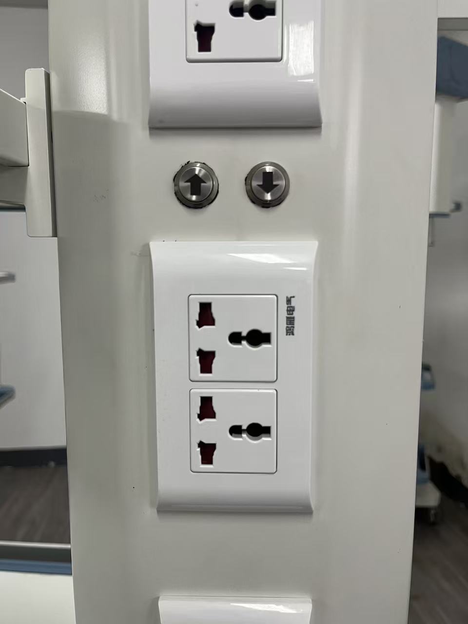
Socket Count, Rating, and Regional Standards
The number and type of power sockets is the most frequently specified electrical parameter, and the most frequently got wrong. The mistake is copying a socket count from a previous project without re-deriving it from the actual device load in the room.
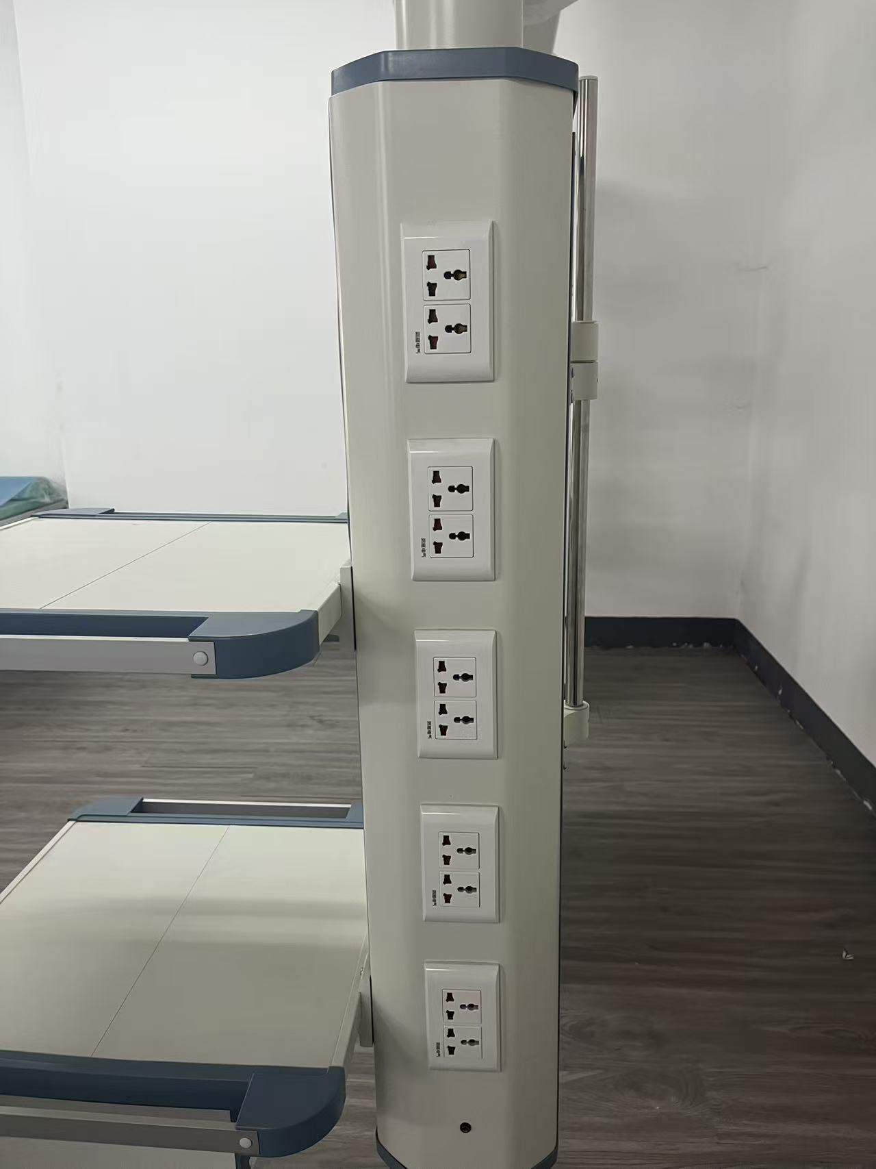
Across the configurations I see, a single-arm theatre pendant commonly carries 6 to 8 medical-grade sockets, while an ICU bridge pendant — serving more devices and sometimes two patient zones — often carries 8 to 12, with the count customizable. The right number comes from a simple load list: enumerate every device, add its nameplate current, apply a diversity factor, and confirm the total stays within the pendant’s rated circuit and the upstream breaker. Undersizing the count forces the clinical team to add trailing extension leads — precisely the uncontrolled wiring that defeats the purpose of a pendant.
Equally important is the socket standard, which must match the plug tops used in your market. A pendant exported to the wrong standard is either useless or dangerous, because adapters introduce resistance, heat, and lost earth continuity. Confirm it in writing against your national wiring rules.
| Parameter | Operating Theatre Pendant (typical) | ICU Bridge Pendant (typical) | What to Confirm at Tender |
|---|---|---|---|
| Power socket count | 6–8 medical-grade outlets | 8–12 outlets (customizable) | Derive from device load list plus diversity; avoid trailing leads |
| Socket standard | Market-specific (e.g., Schuko, BS, NEMA, AS) | Market-specific | Match national wiring rules and device plug tops; no adapters |
| Supply voltage | AC 220–240 V, 50/60 Hz | AC 220–240 V, 50/60 Hz | Confirm against site supply; note 110–120 V markets |
| Group 2 socket type | IT-system-fed sockets where required | As room classification dictates | Colour, switching, and IT-system feed per Section 710 |
| Protection features | Indicator light, leakage/overload protection optional | Indicator light, leakage/overload protection optional | Specify which protections are mandatory for your site |
| Ingress protection | IP20 typical | IP20, upgradable to IP44 in wet zones | Raise IP rating near sinks, scrub areas, or washdown zones |
In Group 2 medical locations, the socket specification is governed by the room’s electrical design, not the pendant catalogue. Wiring regulations require special sockets for life-support, surgical, and monitoring equipment fed from a medical IT system — an isolated power system with an isolating transformer and an insulation monitoring device, so a first earth fault raises an alarm rather than cutting the supply. Those sockets are typically a distinct colour, unswitched, and fed by fire-resistant conductors. Specify this explicitly so the factory does not substitute a standard switched socket where the design calls for an IT-fed outlet.
Network, Data, and Communication Interfaces
Twenty years ago a pendant carried gas and power and little else. Today the data interface list is as contentious as the socket schedule, because the clinical workflow depends on it: monitors stream to a central station, pumps feed clinical information systems, and telemedicine needs video links. If the pendant does not carry the right data drops, those cables end up draped over the arm — a trip hazard and an infection-control problem.
The common data and communication interfaces specified on modern pendants include:
- RJ45 network ports: Typically one or two per pendant for connecting monitors or bedside devices to the hospital LAN. Confirm the category rating (Cat6 or better) and whether the port is simply a pass-through to a ceiling-side patch point or actively switched.
- USB ports: USB-A or USB-C for charging, service connections, or peripheral data. Decide whether these are data-enabled or charge-only, which has security implications.
- Video interfaces: HDMI or similar for displays, surgical cameras, or telemedicine. Optional on most pendants but essential where imaging or teaching is part of the room’s function.
- Nurse-call and VoIP: Dedicated interfaces for nurse-call systems and voice-over-IP, common on ICU bridge pendants.
The integration question is not just which ports to include but how they are cabled back to the hospital infrastructure. Every data port needs a defined route up through the ceiling to a patch panel or switch, respecting the strong/weak separation described earlier. Newer wiring regulations also treat power-over-Ethernet as an extra-low-voltage power source with its own current and cable rules; if you intend to power a device over the pendant’s network port, confirm the cabling and port rating against the applicable standard rather than assuming any RJ45 will do.
Specify data ports against a device list, the same way you specify sockets. An unused RJ45 is cheap; a missing one means drilling the ceiling after the room is commissioned.
A practical approach is to build a single “services schedule” per pendant listing, for each position on the arm or bridge, the gas outlets, power sockets, and data ports, with the cable type and ceiling-side termination for each. Hand that schedule to the pendant factory and the hospital’s IT and biomedical teams so everyone works from one document. For larger rollouts, this is the room-by-room coordination a structured turnkey operating room project should manage for you.
Equipotential Bonding and Protective Earthing
If one electrical topic separates a compliant pendant from a dangerous one, it is equipotential bonding. In a Group 2 medical location the patient may be connected to several devices at once, and even a small potential difference between two pieces of conductive equipment can drive a hazardous current through the patient. The defence is supplementary equipotential bonding: galvanically connecting all exposed and extraneous conductive parts so that, under a fault, everything rises to the same potential.
The pendant is explicitly one of the items that must be bonded. Guidance on supplementary equipotential bonding for medical locations lists operating lights, operating tables, and electrical booms and pendants among the equipment to be bonded, alongside the protective-earth conductor of the branch circuits and the IT-system transformer screen. In practice the pendant must provide dedicated bonding terminals — manufacturers typically fit two to four on an ICU bridge pendant — wired back to the room’s bonding busbar by the shortest practicable route.
The acceptance criterion is concrete and testable. Under the revised Section 710 requirements, the resistance of each supplementary bonding conductor must be measured and recorded, and the value between simultaneously accessible exposed conductive parts must not exceed 0.2 Ω. That is a hard number you can put in your tender and verify on site — one that catches sloppy workmanship, since a pinched, undersized, or poorly terminated bonding conductor will fail it.
- Bonding terminals on the pendant: Confirm the number and rating of equipotential bonding points the pendant provides, and that they are accessible for inspection and testing.
- Conductor sizing: Bonding conductors must be correctly sized (the bonding busbar example referenced in the standards accommodates conductors up to 25 mm²); confirm the pendant’s internal earth and bonding conductors match the design.
- Identification: Each bonding conductor should be identifiable at both ends, and a wiring list provided, so testers can verify each circuit without guessing.
- Recorded test results: Require that the resistance of each supplementary bonding conductor is measured, recorded, and handed over in the commissioning documentation, with a pass threshold of 0.2 Ω.
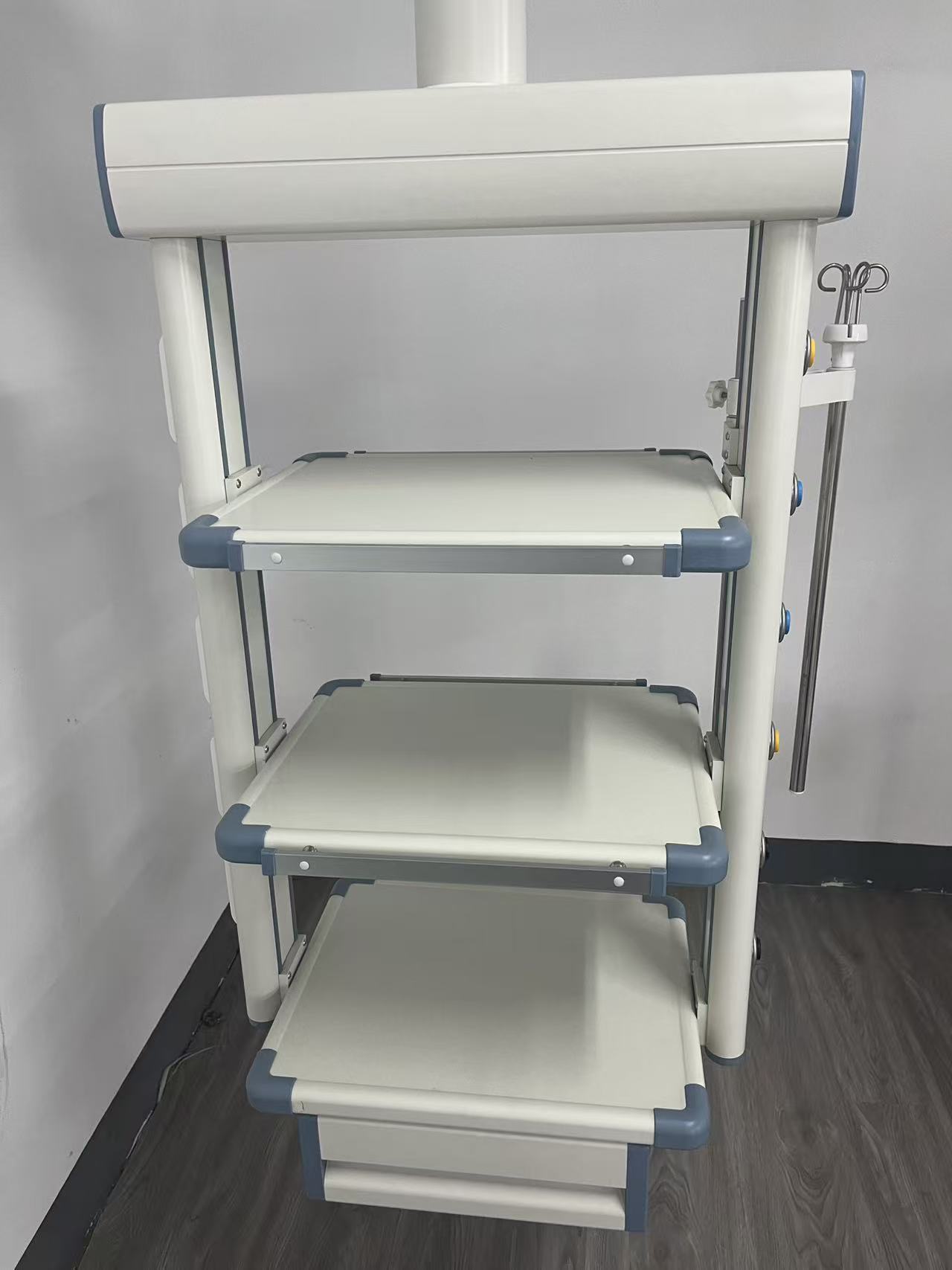
Internal Wiring, Cable Routing, and Serviceability
Everything above assumes the pendant’s internal wiring can be installed, inspected, and maintained without tearing the unit apart. This is where build quality shows: a pendant that looks identical in a brochure can be either a serviceable assembly with labelled, loomed, accessible wiring — or a tight bundle of cables no one can fault-find without removing covers and voiding warranties.
The wiring inside a pendant has to survive movement. Single-arm and bridge pendants rotate, often through 340 degrees or a full 360, and the cables feeding the sockets and data ports on the moving arm must flex repeatedly without fatigue failure. A cable that is too short snaps at the joint; one that is too long chafes against the structure. The routing must also keep cables clear of the gas channels and brake.
- Looming and labelling: Conductors should be grouped into labelled looms with identification at both ends, matching the services schedule. This makes commissioning and later fault-finding dramatically faster.
- Strain relief and grommets: Every cable entry point needs a grommet or gland to prevent chafing, and flexible cords need strain relief so tension never reaches the terminal.
- Fire-resistant conductors: Where the design calls for IT-system supply conductors, confirm the cables meet the required fire-resistance rating for the installation.
- Accessible termination points: The ceiling-side entry and the arm-side outlets should both be reachable for testing and replacement without dismantling the whole pendant.
Serviceability also means thinking about the day a socket fails or a data port needs adding. A pendant with modular, replaceable outlet modules and a reachable wiring bay lets a biomedical engineer swap a faulty socket in minutes; a sealed unit with no service access turns the same fault into a return-to-factory repair. When you evaluate suppliers, ask to see the internal layout and the service manual, not just the rendered exterior. The discipline mirrors planning long-term spares covered in medical pendant maintenance and spare parts — design for the technician who will work on the unit five years from now.
Procurement and Factory Acceptance Checklist
The way to guarantee medical pendant electrical integration is done right is to make it a contractual, testable scope rather than a verbal expectation. The checklist below is what I would attach to a tender and verify at factory acceptance testing (FAT) before the units ship.
- Services schedule per pendant: A documented list of every gas outlet, power socket, and data/communication port, with position, cable type, and ceiling-side termination. No schedule, no approval.
- Cross-section drawing: A drawing showing separate power, data, and gas channels and the segregation standard applied. Verify strong/weak separation is physical, not just claimed.
- Socket standard and rating confirmation: Written confirmation of socket type, voltage, current rating, and any IT-system-fed sockets, matched to your national wiring rules.
- Bonding terminal count and rating: The number of equipotential bonding points and their rating, with conductor sizing to match the design.
- Continuity and bonding test: At FAT, measure protective-earth continuity and the resistance of each bonding conductor; require recorded results with the 0.2 Ω pass criterion for supplementary bonding.
- Insulation and polarity checks: Insulation resistance and polarity verification on every socket circuit before the unit leaves the factory.
- Data port verification: Test each network and data port for continuity and correct termination; certify network ports to the stated category.
- Ingress protection evidence: Where an elevated IP rating is specified for wet zones, request the test evidence or rating certificate.
- Documentation pack: Wiring diagrams, the bonding conductor wiring list, test certificates, and the service manual, all in the project language.
Two commercial points protect you here. First, freeze the services schedule before production starts; changing socket counts or data ports after the loom is built is exactly the late variation that delays a project and invites shortcuts. Second, agree the FAT protocol in the contract so the supplier knows which tests you will witness. A supplier confident in their electrical integration will welcome a clear test protocol; one that resists it is telling you something. If you are unsure how to structure these requirements, a short technical exchange at contact stage can prevent a non-conformance at handover.
Conclusion
Medical pendant electrical integration is not a sub-feature of the pendant; for the clinical team it is the pendant. The gas outlets matter, the arm reach matters, but if the power trips mid-case, the network port was never wired, or the bonding fails its 0.2 Ω test, the room does not go live. Treat the electrical and data scope as a defined engineering deliverable: separate strong and weak current physically, derive the socket count and standard from a real device load, specify data ports against a device list, and insist on bonding that is measured and documented.
The standards give you clear acceptance criteria — IEC 60364-7-710 and its regional adoptions for the installation, IEC 60601-1 for the equipment, and a concrete 0.2 Ω threshold for supplementary bonding. Build those criteria into your tender, attach a services schedule and a factory acceptance test protocol, and verify the results before the units ship. If you would like help defining the electrical and data integration for your theatre or ICU pendants, browse the Sanyang Medical pendant range and bring your services schedule to the conversation.
Frequently Asked Questions
How many power sockets should a medical pendant have?
There is no universal number — it depends on the devices the room uses. As a rule of thumb, a single-arm theatre pendant carries 6 to 8 medical-grade sockets, while an ICU bridge pendant often carries 8 to 12 and may serve two patient zones. Derive the figure from a device load list: add the nameplate current of everything that plugs in, apply a diversity factor, and confirm the total stays within the pendant’s rated circuit. The goal is to eliminate trailing extension leads and adapters, an electrical and infection-control risk.
Why must strong and weak current be separated inside a pendant?
Strong current (mains power) and weak current (data, network, and signal lines) must be kept in separate channels for two reasons. Safety: a fault must never put mains voltage onto a data line running to a patient-connected device. And electromagnetic compatibility: power cables feeding switching loads induce noise onto unshielded data cables, causing intermittent monitor dropouts and corrupted data. Reputable manufacturers route gas, power, and communication lines in separate ducts; ask for a cross-section drawing to confirm the segregation is physical, not claimed.
What is equipotential bonding and why does the pendant need it?
In a Group 2 medical location such as an operating theatre, a patient may be connected to several devices at once, and even a tiny voltage difference between two pieces of equipment can drive a hazardous current through the patient. Supplementary equipotential bonding galvanically connects all exposed and extraneous conductive parts — including the pendant, operating lights, and tables — so that under a fault everything rises to the same potential. The pendant must provide dedicated bonding terminals wired to the room’s bonding busbar, and each bonding conductor measured against a 0.2 Ω pass threshold.
Which data and network ports should I specify on a pendant?
Specify data ports against a device list, just as you do for sockets. Common interfaces include one or two RJ45 network ports (Cat6 or better) for monitors and bedside devices on the hospital LAN, USB-A or USB-C for charging and service, and optionally HDMI for displays or telemedicine; ICU bridge pendants often also carry nurse-call and VoIP. Confirm how each port is cabled back to the hospital infrastructure, respect strong/weak separation in the routing, and if you plan to power a device over Ethernet, verify the cabling and port rating against the applicable standard.
How do I verify the electrical integration before accepting delivery?
Make the electrical and data scope a contractual, testable deliverable and verify it at factory acceptance testing. Require a services schedule per pendant, a cross-section drawing showing power/data/gas segregation, and written confirmation of socket standard and rating. At FAT, insist on protective-earth continuity testing, measurement of each bonding conductor against the 0.2 Ω criterion, insulation and polarity checks on every socket circuit, and verification of each data port. Ask for the documentation pack — wiring diagrams, bonding wiring list, and test certificates — in your project language before the units ship.
You May Also Like...

After-Hours Maintenance Strategy: Minimizing OR Downtime
Operating room downtime is expensive because an idle OR still burns staff, overhead and scheduled...

Operating Table Battery Replacement: Procedure and Intervals
Operating table battery replacement is the routine swap of the integrated backup battery that keeps...

Trolley Lock Cylinder Maintenance: Keyed and Push-Lock Types
Medical trolleys fail at the lock. Not the frame, not the casters, not the drawers...