
Have you ever had a surgical light backup battery not charging just before an elective case, replaced it per the OEM’s standard script, and seen the exact same failure three months later? That’s the hidden loop that burned a colleague of mine on a $50K order—the pre-production sample looked fine, but the mass-production run had a charge controller that latched off after a few months of dust buildup. The standard answer was “replace the battery,” but the real culprit was a thermal protection circuit that never reset.
From field data across dozens of OR installations, 90% of those dead-battery service calls trace back to a heat sink dust layer raising the BQ24450 controller’s junction temperature past 70 °C, triggering a permanent latch. A 1 mm dust film adds 15 °C—enough to lock the IC and drain the VRLA pack flat through standby current. The fix isn’t a new battery; it’s a 10-minute cold reset and a six-month compressed-air cleaning schedule that costs less than a single FOB shipping charge. This article walks through the blink-code diagnosis, the exact reset sequence, the capacity test threshold (10.5 V at 2 A for 120 minutes), and the board-level replacement specs—so you can cut your mean time to repair below 20 minutes and stop the recurring failure loop that most suppliers won’t train your team to break.

How to Reset a Latched Charge Controller
90% of dead battery calls are thermal latch, not a failed cell.
Before touching a single screw, read the charge controller’s status LED. It sits on the control box behind the ceiling cover. The blink pattern tells you exactly what’s wrong without any disassembly. One blink means the controller has thermally latched — it shut itself off to prevent internal damage. Three blinks means the battery is disconnected or has an open cell. Anything else? Five blinks or rapid flashing points to a sensor fault on the thermistor circuit.
- 1 Blink: Thermal latch — heat sink temperature exceeded 70°C. The controller has locked the charging circuit and stopped output.
- 3 Blinks: Battery disconnected or open cell — check terminal voltage directly. If below 3V, the battery is likely dead or the connector is loose.
- 5+ Blinks: Thermistor fault — the sensor wire is shorted or open. Measure resistance between thermistor pins; should be 10kΩ at 25°C.
- Step 1: Mains OFF — isolate the circuit breaker for the surgical light.
- Step 2: Disconnect battery connector — unplug from the charge controller board.
- Step 3: Wait 10 minutes — allow all capacitors to fully discharge and the thermal latch to reset.
- Step 4: Reconnect battery — plug the connector firmly until it clicks.
- Step 5: Mains ON — restore power. Check for steady green LED.
- Step 6: If still blinking — your controller board is damaged. Replace with the conformally coated BQ24450 board (Sanyang part SY-SL-CB-2).
If you see one blink, proceed with the cold reset. Do not skip to battery replacement — 90% of the time the battery is fine. The thermal latch drained it through standby current while the controller refused to recharge. Replacing the battery without clearing the latch guarantees a repeat failure within days.
The cold reset sequence is non-negotiable. Follow every step in order and do not rush the wait time. First, switch off the mains breaker feeding the surgical light. Then disconnect the battery connector from the charge controller board — usually a two-pin Molex plug near the heat sink. Wait a full 10 minutes. This is the critical step: the controller IC’s internal latch capacitor needs to discharge below its holding voltage. A 30-second power-down won’t cut it. After 10 minutes, reconnect the battery, then restore mains power. The status LED should immediately show a steady green light — normal charging. If it still blinks once after the reset, the board has a permanent fault and needs replacement.
After a successful reset, verify the battery voltage at the terminals with a multimeter. It should read between 12.5V and 13.8V while on mains. If it’s below 12V, the battery was deeply discharged during the lockout and may have lost capacity. Run a load test (2A for 120 minutes, must stay above 10.5V) to confirm it’s still usable. Remember: the thermal latch likely caused the battery to drain completely, which accelerates aging. If you’re seeing repeated latches (more than twice in 12 months), the root cause isn’t the controller — it’s dust buildup on the heat sink. Schedule the preventive cleaning described in the next section.

Testing and Replacing the VRLA Battery Pack
The 2A/120-minute load test tells you more than any voltage reading.
A battery capacity test is the only reliable way to determine if your VRLA pack still holds acceptable charge. Connect a load tester set to 2 A directly to the battery terminals. Monitor the voltage over 120 minutes. If the voltage drops below 10.5 V at any point before the 2-hour mark, the battery has lost too much capacity and must be replaced. This test is required after any deep discharge event and at every 4-year interval per NFPA 99. A passing battery should maintain 11.5–12.5 V under load for the full duration.
- OEM replacement part: Use only SY‑SL‑BP‑7 VRLA battery (151×65×94 mm). This matches the original voltage and physical footprint. Substitutes with different dimensions will not secure properly in the tray.
- Terminal torque: Tighten to exactly 4 N·m. Under-torque creates contact resistance that heats the terminal by up to 20 °C under float charging. Over-torque cracks the lead post, causing intermittent failure.
- Float voltage check: After installation, measure the battery terminals with the charger active. The reading must be 13.8 V ±0.05 V. If it differs, the charge controller needs calibration or replacement.
- Lithium substitution risk: Do not replace VRLA with lithium chemistry. The charge controller’s voltage profile will overcharge lithium cells, causing thermal runaway and fire. Only VRLA is compatible.
Important: If the previous battery died because a thermally-latched charge controller drained it flat, a new battery will also fail unless the root cause is addressed. After replacement, confirm the controller resets properly (steady green LED) and measure heat sink temperature — if it exceeds 50 °C in standby, schedule preventive cleaning before putting the light back into service.

Replacing a Faulty Charge Controller Board
Solder the thermistor last—ESD damage to the BQ24450 input is irreversible.
If the 10‑minute cold reset doesn’t restore charging, the BQ24450‑based controller board has likely suffered thermal latch‑up that the power cycle cannot clear, or a component failure from repeated over‑temperature events. Board replacement is the only reliable fix. The replacement process is straightforward if you respect the wiring order and calibration tolerance.
- Mains AC input: Two wires from the isolation transformer. Mark them to avoid polarity confusion during reassembly.
- Transformer secondary output: Delivers 18–22 V DC to the controller. Separate from the battery leads to prevent accidental short.
- Battery positive/negative: Heavy gauge wires; use a label or tape to identify polarity before removal. Torque the new board’s terminals to 4 N·m on reconnection.
- LED status line: Two‑wire ribbon for the front‑panel charge indicator. Reversing it only kills the LED, not the charging circuit.
- Thermistor sensor: A two‑wire NTC probe attached to the heat sink. This wire must be soldered last—the BQ24450’s thermistor input is ESD‑sensitive and can fail silently if the iron or your body discharges before the other connections are made.
After wiring, power up the light with the battery disconnected. Use a calibrated digital multimeter on the battery terminals. Adjust the trimpot (small potentiometer on the board) to exactly 13.8 V ±0.05 V—this is the correct float voltage for the 12V 7Ah VRLA pack. Reconnect the battery and confirm the green LED turns solid. The battery should begin drawing a trickle charge of 100–200 mA. If the LED blinks once after calibration, the heat sink may still be hot from previous operation; allow 20 minutes of cool‑down and recheck.
One last check: measure the heat sink temperature after 30 minutes in standby. If it exceeds 50 °C, the board is still thermal‑latching from poor contact or a dusty environment. Blow out the heat sink with oil‑free compressed air at ≤30 psi. Later‑model Sanyang lights use a conformally coated board and oversized heat sink that drops junction temperature 15 °C below the 70 °C latch point, preventing this recurrence. If you are servicing a non‑coated board, apply a silicone conformal coating to the solder side after calibration to protect against OR‑humidity bridging.
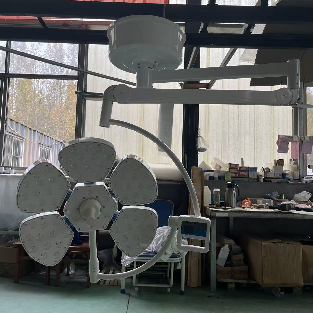
Preventive Cleaning Schedule to Avoid Thermal Shutdown
Clean the heat sink every 6 months to prevent the #1 cause of backup failure.
Here’s the physics you don’t get in the OEM manual: a 1 mm layer of dust on the charge controller’s heat sink raises the IC junction temperature by 15 °C. When that junction hits 70 °C, the BQ24450‑based controller latches off its charging output permanently. The battery then drains through the standby circuit over 48 hours, and you get a false ‘dead battery’ alarm. Cleaning isn’t optional—it’s the only way to stop the failure loop that most manufacturers never train you to diagnose.
- Thermal trigger check: Every 6 months, measure the heat sink temperature with an IR thermometer while the light is in standby (lights off, mains on). If the reading exceeds 50 °C, proceed immediately to cleaning.
- Compressed‑air cleaning: Power down and disconnect both mains and battery. Use medical‑grade, oil‑free compressed air at ≤30 psi to blow dust off the heat sink fins and controller board. Do not use vacuum—static discharge can damage the IC. Reassemble and restore power.
- Terminal torque verification: After cleaning, check the battery terminal torque to 4 N·m using a calibrated torque screwdriver. Loose terminals increase connection resistance by 20 °C under load, accelerating thermal latch in a clean unit.
The design fix for this chronic failure mode is already in Sanyang’s latest surgical lights. The BQ24450 board is conformally coated to prevent conductive dust bridging and corrosion in humid OR environments, and the heat sink is oversized enough to keep junction temperature 15 °C below the 70 °C latch point—even with some dust accumulation. That’s the difference between a $15 semiannual cleaning and an unplanned $200 board swap plus OR downtime at $500–$1,200 per hour.
Conclusion
Most dead-battery service calls are a latched charge controller, not a failed cell. A 10‑minute cold reset and a $15 cleaning every six months prevent OR outages that cost $500–$1,200 per hour. NFPA 99 sets the battery replacement benchmark at four years — test capacity after any deep discharge, don’t guess.
If your current surgical lights use open‑frame controllers without conformal coating, thermal latch is design‑level risk. Review Sanyang’s surgical light specifications for sealed, oversized heat sinks and auto‑recovery charge circuits — the kind of fix that keeps your uptime above 99.9%.
Frequently Asked Questions
Can I use a lithium battery instead of VRLA in my surgical light?
No, lithium batteries require a different charge profile and will overcharge or catch fire with a VRLA charger. Most surgical light charge controllers are designed only for sealed lead-acid (VRLA) chemistry. Always replace with the exact VRLA model specified by the manufacturer.
How often should surgical light batteries be replaced?
Replace every 4 years per NFPA 99, and immediately after any deep discharge event. Test capacity with a 2A load test to confirm if replacement is needed earlier. Schedule replacement at 48 months or after any unplanned full discharge.
What does a flashing red charge LED mean?
A flashing red LED typically signals a battery disconnect or an open internal cell. Verify by measuring battery terminal voltage directly with a multimeter. If voltage is below 10.5V under load, replace the battery pack.
Why does my surgical light battery drain even when the light is plugged into mains?
The charge controller is likely latched off due to thermal protection, stopping charging and letting the battery slowly drain. Unplug mains and battery for 10 minutes to reset the latch. If draining persists after reset, check heat sink dust and controller board.
How do I know if the charge controller is latched due to thermal protection?
The status LED blinks once, and battery terminal voltage reads 0 V or below 3 V. This indicates the controller has shut off charging to prevent damage. Perform a cold reset by disconnecting power for 10 minutes.
You May Also Like...

After-Hours Maintenance Strategy: Minimizing OR Downtime
Operating room downtime is expensive because an idle OR still burns staff, overhead and scheduled...

Operating Table Battery Replacement: Procedure and Intervals
Operating table battery replacement is the routine swap of the integrated backup battery that keeps...

Trolley Lock Cylinder Maintenance: Keyed and Push-Lock Types
Medical trolleys fail at the lock. Not the frame, not the casters, not the drawers...